


IV
Part Descriptions
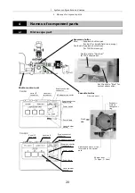
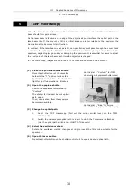
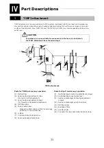
1 TIRF2 attachment
34
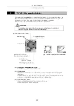
(1) Optical-fiber
cable
This cable conducts laser beam from the laser unit to the TIRF2 attachment.
•
To ensure specified performance and to protect your eyes and skin from
exposure to the laser, do not detach the optical-fiber cable from the
TIRF2 attachment.
•
To prevent damage to wires, do not bend the optical-fiber cable or pull
it with excessive force.
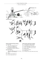
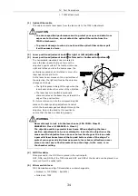
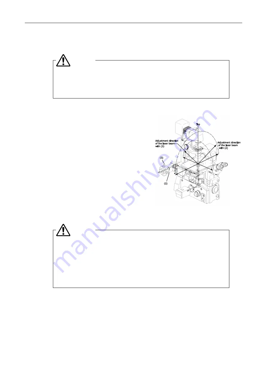
(2) Laser position adjustment knob
(
for right or left adjustment
)
(3) Laser position adjustment knob
(
for forward or backward adjustment
)
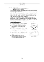
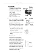
The horizontally-mounted knob is rotated to
move the laser beam focal point across the
objective's pupil surface. The focal point moves
right and left as you face the microscope. The
vertically-mounted knob is rotated to move the
laser beam back and forth.
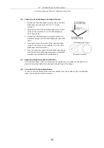
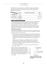
As the laser beam moves on the pupil surface of
the objective, the light emitted by the objective
changes as follows:
•
The light is passed straight through when the
laser beam strikes the center of the objective.
•
The laser beam is emitted at gradually
sharper angles as the beam moves toward the
edge of the pupil surface.
For future reference, note the corresponding tick
mark on the laser position adjustment knob at
which the laser beam passes straight through the
objective. Return the knob to this position to
ensure that the beam is directed properly.
Never attempt to look into the laser beam. (FDA CDRH: Class II,
EN60825-1: Class 2, IEC60825-1: Class 2)
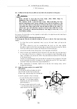
The objective emits a powerful laser beam. When adjusting the laser
position adjustment knob, never attempt to look into the objective or the
areas near the objective from above or below the stage as the lens emits
a powerful laser beam toward the top and bottom sides of the stage. To
protect your eyes and skin from exposure to laser beam reflections, never
place or mount any reflective materials on the stage, in the room, or on
the chamber ceiling.
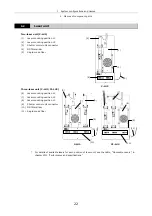
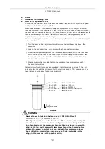
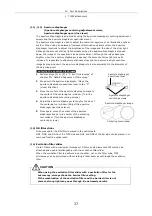
(4) ND
filter
slider
Once pressed in, the ND filter is placed in the optical path.
ND2, ND8, and ND16 of the TIRF side and ND4 and ND8 of the Epi side can be placed in or
removed from the optical path.
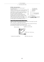
(5) Mirror switch lever
TIRF illumination and Epi-fl illumination are interchangeable.
•
Pressed in: TIRF(60%) - Epi(40%)
•
Pulled out: TIRF
CAUTION
WARNING
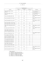
Summary of Contents for TIRF2
Page 1: ...TIRF2 SYSTEM FOR TE2000 INSTRUCTIONS M339E 04 12 NF 2 ...
Page 2: ......


