


III
Detailed Sequence of Microscopy
5 TIRF microscopy
31
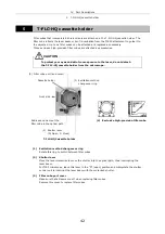
(6) Collimate the laser beam (Perform each time the objective is changed).
Never attempt to look into the laser beam. (FDA CDRH: Class II,
EN60825-1: Class 2, IEC60825-1: Class 2)
The objective emits a powerful laser beam. When adjusting the laser
position adjustment knob, never attempt to look into the objective or the
areas near the objective from above or below the stage as the lens emits
a powerful laser beam toward the top and bottom sides of the stage. To
protect your eyes and skin from exposure to laser beam reflections, never
place or mount any reflective materials on the stage, in the room, or on
the chamber ceiling.
By focusing the laser beam on the objective’s pupil surface, the objective-emitted laser beam
should form parallel rays.
Never look through the objective during this work.
It is dangerous because accidental exposure of eyes or skin to the laser beam may
occur.
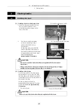
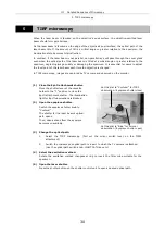
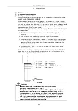
1. Turn the laser position adjustment knob to move the laser beam just above the
objective.
(For future reference, note the corresponding tick mark on the laser position
adjustment knob at which the laser beam passes straight through the objective. Return
the knob to this position to ensure that the beam is directed properly.)
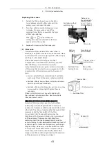
2. Loosen the condenser lens locking screw with a hexagonal screwdriver.
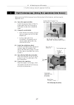
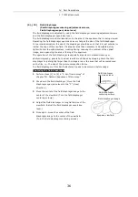
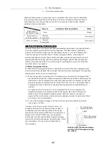
3. Move the focal point adjustment knob back and forth while observing the laser beam
on the ceiling of the room or chamber. Try to minimize the spot illuminated by the
laser; or at least try to reduce the width of the illuminated spot smaller than the double
of the minimum size.
(Indices (circumferential grooves) are provided to indicate various positions of the focal
point adjustment knob that correspond to the objectives used for TIRF observation.
Use these indices to guide laser focal point adjustment.)
4. When adjustment is complete, tighten the condenser lens locking screw with a
hexagonal screwdriver.
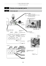
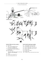
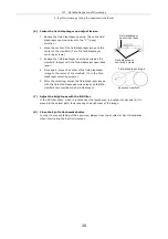
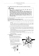
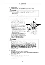
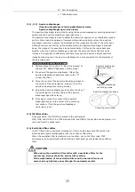
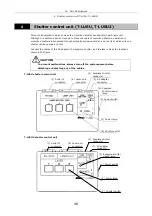
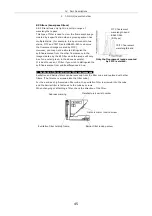
(7) Adjust the laser position to provide TIRF
illumination.
Turn the laser position adjustment knob to
make the laser beam focus on the pupil
surface edge, thus providing TIRF illumination.
Across the eyepiece of the microscope,
•
To move the focal point to forward or
backward:
Turn the laser position
adjustment knob A (knob located in
vertical direction).
•
To move the focal point to left or right:
Turn the laser position adjustment knob B
(knob located in horizontal direction).
WARNING
B
A
Summary of Contents for TIRF2
Page 1: ...TIRF2 SYSTEM FOR TE2000 INSTRUCTIONS M339E 04 12 NF 2 ...
Page 2: ......


