background image


52 

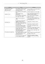
Troubleshooting Tables

VI 

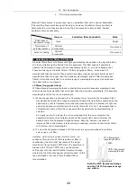
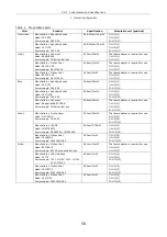
Improper use of the microscope may adversely affect performance, even if the microscope is not 
damaged. If any of the problems listed in the table below arise, take the countermeasures indicated. Also 
refer to the instruction manual supplied with the microscope, light source and the DIC attachment (If DIC 
attachment is also used). 


1. Epi-fl 

microscopy 

Problem 

Cause 

Remedy 

The power supply is not 

plugged in. 

Plug the power cord into an outlet. 

The lamp connector is not 

connected to the power supply.

Connect the lamp connector to the 

power supply. 

The lamp has reached the end 

of its operational life. 

Replace the lamp. 

Lamp does not light. 

The fuse is blown. 

If the fuse can be replaced, replace 

it. Otherwise, contact your nearest 

Nikon representative. 

The shutter is in the optical 

path. 

Remove the shutter from the optical 

path. 

The filter cube has stopped at 

an intermediate position. 

Rotate the excitation method 
changeover ring to the clickstop 

position. 

The filter cube selection is 

incorrect. 

Select the correct filter cube. 

The combination of excitation 
filter, barrier filter and dichroic 

mirror is inappropriate, or one 

of these components is 

missing. 

Use a filter cube with a correct 

combination. 

The setting is still for TIRF 

microscopy. 

Push in the mirror switch lever to 

change to Epi-fl microscopy. 

The eyepiece shutter is not set 

to “Bino” . 

Change to “Bino” . 

Even though the lamp is on, 

the image is not visible. 

The microscope’s optical path 

is not set to “Observation” . 

Point the optical path at the 
binocular eyepiece with the optical 

path switch knob or LIGHT PATH 

switch. 

The light source is not 

centered properly. 

Center the lamp. Especially when 
using a 100x objective, recenter the 

lamp while observing the fluorescent 

image. 

ND filters are in the optical 

path. 

If necessary, remove the ND filters 

from the optical path. 

The combination of excitation 
filter, barrier filter and dichroic 

mirror is inappropriate for the 

specimen. 

Use a filter cube with a combination 

suited for the specimen. 

A halogen lamp is being used 

with a dark specimen. 

Change the light source to a mercury 

lamp. 

Even though the lamp is on, 

the image is extremely dark. 

The designated objective is not 
being used with UV or V 

excitation. 

Use the designated objective. 


Summary of Contents for TIRF2

Page 1: ...TIRF2 SYSTEM FOR TE2000 INSTRUCTIONS M339E 04 12 NF 2 ...

Page 2: ......

Page 3: ...nning of this manual No part of this manual may be reproduced or transmitted in any form without the prior consent of Nikon The contents of this manual are subject to change without notice Every effort has been made to ensure the accuracy of this manual If you find that any portion of this manual is unclear or incorrect please contact your nearest Nikon representative This manual may describe prod...

Page 4: ... Caution for heat This marking at the top part of the Dia illuminator and the 12V100W lamphouse calls your attention on the following Lamphouse becomes very hot during and immediately after the illumination Risk of burns Do not touch the lamphouse during and immediately after the illumination Make sure that the lamphouse is sufficiently cool before the lamp replacement Biohazard This symbol on the...

Page 5: ...ed below are in place Removal of any part during use may result in unintended exposure of eyes or skin to laser light Make sure that all power to the laser and entire system is turned off when removing an objective or filter cube Eyepiece tube nosepiece objective TIRF2 attachment filter cube stage lamphouse cassette holder for Epi fl microscopy TV camera all port caps 5 Do not disassemble Disassem...

Page 6: ...source and the manual if provided by the manufacturer of the lamp and follow their instructions The Hazards of Mercury Lamps 1 Mercury lamps radiate ultraviolet light that is harmful to the eyes and skin when they are turned on Direct viewing of light from these lamps may result in blindness 2 Gas is sealed under very high pressure inside the lamps The pressure increases when the lamp is on If the...

Page 7: ...r To prevent malfunction always turn off the power switch switch to O of the shutter control unit before attaching the AC adapter 3 Cable connections Always switch off the power switches to all equipment before connecting or disconnecting cables To prevent broken wires do not pull cables by the sheath instead firmly grasp the plug when connecting or disconnecting a cable 4 Response if the system o...

Page 8: ...his product is not subject to strong vibrations which may degrade image quality Consult with your Nikon representative about preventive measures you may take when this product is installed To prevent degradation malfunction or failure of your laser units and PC always use power supply that is free from electric noice or sudden voltage fluctuations To prevent failure do not block or place any obsta...

Page 9: ...ty check 24 2 Startup tasks 25 2 1 Emitting the laser 25 2 2 Turning on power to other components 26 3 Epi fl microscopy bring the specimen into focus 27 4 Simple surface reflection interference microscopy using Epi fl attachment checking the state where the specimen contacts to the cover glass 29 5 TIRF microscopy 30 6 Termination tasks 32 IV Part Descriptions 33 1 TIRF2 attachment 33 2 Specimen ...

Page 10: ...m charged 56 8 Periodical inspection charged 56 VIII Performance and Specifications 57 1 Overall configuration 57 1 1 Shutter control unit 60 1 2 AC adapter for shutter control unit 60 1 3 Power cord for AC adapter of shutter control unit 60 1 4 Environment 60 1 5 Compatible standards 61 ...

Page 11: ...hutter control unit 6 AC adapter 7 TV camera 8 Eyepiece shutter 9 Cassette holder 10 Power supply for microscope 11 TIRF2 attachment 12 Light source for the Epi illumination attachment Super high pressure mercury lamp housing is indicated in the figure 13 Power supply of the light source for the Epi illumination attachment Power supply of the super high pressure mercury lamp is indicated in the fi...

Page 12: ...tter control unit 6 AC adapter 7 TV camera 8 Eyepiece shutter 9 Cassette holder 10 Power supply for microscope 11 TIRF2 attachment 12 Light source for the Epi illumination attachment Super high pressure mercury lamp housing is indicated in the figure 13 Power supply of the light source for the Epi illumination attachment Power supply of the super high pressure mercury lamp is indicated in the figu...

Page 13: ...shutter 5 ND filter ND4 ND8 6 Laser synthesis mirror 7 Laser out single mode fiber Laser mounting position L1 L2 L3 Two laser unit C LU2 405nm to 514nm 532nm to 640nm Three laser unit C LU3 405nm to 440nm 633nm to 640nm 488nm to 514nm 532nm to 561nm Three laser unit C1 LU3 488nm to 514nm 532nm to 543nm 594nm to 633nm 2 1 3 7 2 1 4 5 3 7 6 1 4 5 2 7 6 Two laser unit C LU2 Three laser unit C LU3 Thr...

Page 14: ...I System configurations and names 2 Laser path 12 2 2 Microscope part 1 TE2000 MICROSCOPE 2 TE2000 MICROSCOPE from top Laser beam Laser beam ...

Page 15: ...ety labels 1 IEC laser warning label hazard symbol 2 IEC explanatory label Class 2 laser product 3 Model name and serial number label 4 Safety standard label 5 IEC caution label Class 3B areas 6 IEC caution label Class 2 areas 7 IEC caution label Class 2 areas ...

Page 16: ...I System configurations and names 3 Safety labels 14 3 1 TE2000 1 IEC laser warning label hazard symbol 2 IEC explanatory label Class 2 laser product Labels on stage 2 1 ...

Page 17: ...I System configurations and names 3 Safety labels 15 3 2 Two laser unit C LU2 1 IEC laser warning label hazard symbol 5 IEC caution label Class 3B areas 5 1 ...

Page 18: ...I System configurations and names 3 Safety labels 16 3 3 Three laser unit C LU3 1 IEC laser warning label hazard symbol 5 IEC caution label Class 3B areas 5 1 ...

Page 19: ...I System configurations and names 3 Safety labels 17 3 4 Three laser unit C1 LU3 1 IEC laser warning label hazard symbol 5 IEC caution label Class 3B areas 5 1 ...

Page 20: ...I System configurations and names 3 Safety labels 18 3 5 Shutter control unit T LUSU T LUSU2 4 Safety standard label Back This label is used on both of the T LUSU and T LUSU2 4 ...

Page 21: ...I System configurations and names 3 Safety labels 19 3 6 TIRF2 attachment 3 Model name and serial number label 6 IEC caution label Class 2 areas 7 IEC caution label Class 2 areas 3 6 7 ...

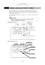
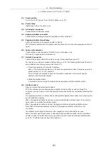
Page 22: ...et the dial to Bino for normal observation Serial IF connector Laser unit connector Power switch Power lamp Laser shutter switch Filter cube port Front side Address and name of the filter cube in the optical path Shutter lever O Open C Close Excitation method changeover ring T LUSU AC adapter connector Eyepiece shutter closed lamp Laser shutter switch Power lamp Power switch Eyepiece shutter close...

Page 23: ...ver Pressed in TIRF 60 Epi fl 40 microscopy Pulled out TIRF microscopy 6 Indices 7 Condenser lens locking screw 8 Focal point adjustment knob Parts for Epi fl microscopy operation 9 Field diaphragm centering screws 10 Field diaphragm open close lever 11 Aperture diaphragm centering screws 12 Aperture diaphragm open close lever 13 ND filter slider 14 Excitation filter slider 15 Shutter slider 16 Co...

Page 24: ... 5 Single mode fiber Three laser unit C LU3 C1 LU3 6 Laser mounting position L1 7 Laser mounting position L2 8 Laser mounting position L3 9 Shutter control unit connector 10 ND filter slider 11 Single mode fiber For details of available lasers for each position of laser unit see the table Mountable Lasers in chapter VIII Performance and specifications 2 3 1 5 4 7 8 11 10 9 6 7 10 9 C LU3 C1 LU3 8 ...

Page 25: ...attachment shutter Bring the specimen into focus Center the field diaphragm and adjust its size Adjust the brightness with the ND filter Close the Epi fl attachment shutter 4 Simple surface reflection interference microscopy Checking the state where the specimen contacts to the cover glass Change the excitation method settings Place the filter cube which has settings of G excitation Dichroic mirro...

Page 26: ...anual for the relevant microscope to adjust the diopter and the interpupillary distance 1 Safety check This product uses class IIIb lasers The laser is harmful light Accidental exposure of eyes or skin to laser light may result in injury or other problems if laser light is irradiated through any opening other than the objective Be sure to execute the following safety check every time before emitti...

Page 27: ...truction Manual supplied with the air cooled argon laser Always select Run mode when using the air cooled argon laser Image quality may be degraded if Run mode is not selected 2 Emitting other lasers Turn the key switch on the laser power unit clockwise to turn on the unit With the three laser unit another key switch is provided on the unit this key switch is also turned clockwise The laser emissi...

Page 28: ...ilter To prevent the intensity of the laser from degrading the sample we recommend inserting an ND filter ND4 or ND8 into the optical path in advance ND filter 2 2 Turning on power to other components Turn on the microscope Epi illumination lamp shutter control unit camera etc ...

Page 29: ...H key etc 3 Select the excitation method Rotate the excitation method changeover ring and change the excitation filter slider of the illumination system to insert the filter cube and excitation filter for the specimen 4 Open the Epi fl attachment shutter Move the shutter lever to the O open position to open the optical path of the Epi fl illumination 5 Focus on the specimen Place the specimen on t...

Page 30: ...aphragm image to the center of the viewfield Turn the field diaphragm centering screws 5 After the centering adjust the field diaphragm image with the field diaphragm open close lever so that the viewfield circumscribes the field diaphragm 7 Adjust the brightness with the ND filter If the ND filter slider which is located near the lamphouse is pushed into backward it is placed in the optical path ...

Page 31: ... settings Before performing TIRF microscopy find out the object by Epi fl microscopy and then bring the object into focus Setup 1 Place the filter cube which has settings of G excitation Dichroic mirror for UV and No barrier filter in the optical path 2 Set the aperture diaphragm to or as close as possible the minimum setting 3 Adjust the filed diaphragm opening to the minimum setting required for...

Page 32: ... by TV camera and observed on the monitor 1 Close the Epi fl attachment shutter Move the shutter lever of the cassatte holder to the C position to close the Epi fl attachment shutter The illumination light for Epi fl observations is blocked 2 Open the eyepiece shutter Switch the eyepiece shutter knob to Confocal The shutter for the laser beam s optical path opens Then observations from the eyepiec...

Page 33: ...ment knob at which the laser beam passes straight through the objective Return the knob to this position to ensure that the beam is directed properly 2 Loosen the condenser lens locking screw with a hexagonal screwdriver 3 Move the focal point adjustment knob back and forth while observing the laser beam on the ceiling of the room or chamber Try to minimize the spot illuminated by the laser or at ...

Page 34: ...laser remote controller and leave it for approximately 15 minutes to sufficiently cool down the laser head After checking that it is sufficiently cool switch off the key switch and then power switch which are on the power unit 2 Turn off the Epi illumination lamp The lamp stays very hot because of lighting If you want to put a cover on the lamp be sure to at least wait 30 minutes after the lamp go...

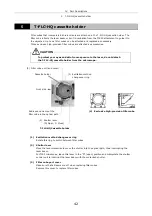
Page 35: ...2 microscopy operation 1 Optical fiber 2 Laser position adjustment knobs for right or left adjustment 3 Laser position adjustment knobs for forward or backward adjustment 4 ND filter slider 5 Mirror switch lever Pressed in TIRF 60 Epi fl 40 microscopy Pulled out TIRF microscopy 6 Indices 7 Condenser lens locking screw 8 Focal point adjustment knob Parts for Epi fl microscopy operation 9 Field diap...

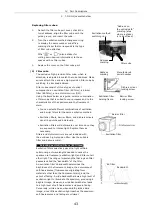
Page 36: ... emitted at gradually sharper angles as the beam moves toward the edge of the pupil surface For future reference note the corresponding tick mark on the laser position adjustment knob at which the laser beam passes straight through the objective Return the knob to this position to ensure that the beam is directed properly Never attempt to look into the laser beam FDA CDRH Class II EN60825 1 Class ...

Page 37: ...amber Try to minimize the spot illuminated by the laser or at least try to reduce the width of the illuminated spot smaller than the double of the minimum size 4 When adjustment is complete tighten the condenser lens locking screw with a hexagonal screwdriver Indices circumferential grooves are provided to indicate various positions of the focal point adjustment knob that correspond to the objecti...

Page 38: ...rtant in videomicroscopy or photomicrography generally the best results are obtained by stopping down the field diaphragm to just slightly larger than the image area or the area that will be reproduced on the film i e the size of the picture composition frame The field diaphragm of this Epi fl attachment needs to be centered before usage Centering the field diaphragm 1 Perform steps 1 to 5 in 3 Ep...

Page 39: ...pen close lever to the C close direction 3 Move the center of the aperture diaphragm image to the center of the centering tool window Turn the aperture diaphragm centering screws 4 Adjust the aperture diaphragm to roughly the size of the centering tool window Adjust the aperture diaphragm open close lever 5 Once again move the center of the aperture diaphragm image to the center of the centering t...

Page 40: ...r This cover employs a filter that can attenuate the intensity of light in the proximity of 488 nm and 532 nm wavelengths by a factor of up to 1000 Make sure that the cover is always in place except when you are adjusting the laser focal point Specimen cover ...

Page 41: ...the binocular eyepiece during TIRF observation while the mechanism closes the shutter in the laser unit during normal observation observation using eyepieces so that the laser beam is not guided into the TIRF2 attachment An illumination pillar switch to be mounted on the microscope s illumination pillar is supplied with the eyepiece shutter However ignore this switch as this switch s function is n...

Page 42: ...the cables of the AC adapter the eyepiece shutter and the laser unit at the locations shown in the figure To prevent malfunctions always turn off the system power before attaching or detaching any of the cables CAUTION 1 Power switch 2 Power lamp 8 Shutter switch 3 AC adapter connector 4 Eyepiece shutter connector 6 Laser unit connector 7 Serial IF connector 5 Eyepiece shutter closed lamp 6 Laser ...

Page 43: ...riod 0 1 to 100 seconds The shutters are switched to timer set operation mode even when operating the shutters with the shutter switch Disabling shutter switch A command can be issued to disable shutter operation with the shutter switch 8 Shutter switch Opens or closes the motorized shutters With the microscope mounted eyepiece shutter closed so that no light entering the eyepiece you can open or ...

Page 44: ...scope T FLC HQ Cassette holder 4 Exclusive high precision filter cube 1 Excitation method changeover ring Rotate this ring to switch between filter cubes 2 Shutter lever Move the lever clockwise to move the shutter into the optical path thus interrupting the laser beam For TIRF microscopy leave this lever in the O open position and manipulate the shutter control unit to interrupt the laser beam wi...

Page 45: ...deteriorate over time since they are exposed to intense light Replace them as necessary Filters and dichroic mirrors are not included with the exclusive high precision filter Use the suitable filter and dichroic mirror 1 Selecting excitation filters EX filters Excitation filters selectively pass the light within a certain range of wavelengths needed to cause the specimen to fluoresce excitation li...

Page 46: ...longer than the boundary wavelength The boundary wavelength is called the cut on wavelength 1 When the specimen is stained with a fluorescent color for which the fluorescent light wavelength band and the excitation wavelength band the light that is absorbed by the specimen in order to fluoresce are extremely close together the fluorescent light can generally be seen most effectively if a barrier f...

Page 47: ...le It is best to use an LP filter if you wish to distinguish the self fluorescence from subtle differences in hue 3 Excitation filter and barrier filter replacement Excitation and barrier filters can be removed from the filter cube and replaced with other filters The filters are screwed into the filter cube For the exclusive high precision filter cube the excitation filter is screwed into the cube...

Page 48: ...front of each laser head Each laser is equipped with a software controlled motorized shutter The laser head and optical fiber of this unit are precisely aligned Avoid subjecting the laser head or optical fiber to vibration or shock Contact the distributor if you need to remove the laser head from the unit due to laser malfunction or for other reasons 1 ND filter slider ND4 Slider status and transm...

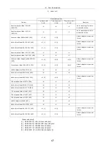
Page 49: ...is required for use Crysta Laser Model GCL 025 S 532 L2 2 L3 2 L2 2 A laser adapter is required for use LASOS Model LGK7786P75 543 L2 L3 L2 Melles Griot Model 05LGP193 543 L2 L3 L2 Melles Griot Model 85YCA010 561 L2 2 L3 2 A laser adapter is required for use JDS Uniphase Model 1677P 594 L2 L1 L3 Melles Griot Model 05LYR173 594 L2 L1 L3 Melles Griot Model 05LYP173 594 L2 L1 L3 JDS Uniphase Model 11...

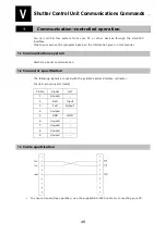
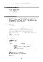
Page 50: ...on given in this manual 1 1 Communications system Start stop serial communication 1 2 Connector specification The following signals are used with the system s serial interface connector D sub 9 pin connector male Pin No Signal I O 1 Unused 2 RxD Input 3 TxD Output 4 Unused 5 GND GND 6 Unused 7 Unused 8 Unused 9 Unused 1 3 Cable specification To ensure trouble free operation use the supplied RS 232...

Page 51: ...ived 1 5 1 Command format A BBB C C CR A Command identifier one lower case alphabet character ASCII code one byte Identifier Description c Operation control and data setting command r Data request command BBB Command name three upper case alphabet characters ASCII code three bytes C C Parameter ASCII code CR Carriage return 0x0D 1 5 2 Response format D BBB E E CR LF D Response identifier Identifie...

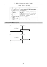
Page 52: ...eived data exceeds the permissible amount 32 bytes 6 Command overflow Number of commands that can be processed is exceeded during continuous transmission of commands five commands 7 Processing inhibit error Processing is inhibited 8 Processing stop error Command processing is stopped 1 6 Communications sequence PC TIRF2 system c command o or n response Command processing TIRF2 system PC r command ...

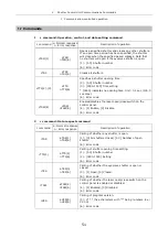
Page 53: ...ime Unit 0 1 sec 100 0 sec max 6 Error code cTSW 4 oTSW nTSW 6 Enables disables the laser open close switch on the control panel 4 1 Enable 0 Disable 6 Error code 2 r command Data request command r command a Normal response n Error response Description of operation rTSR aTSR 1 nTSR 6 Calling of whether any shutter is open 1 0 All shutters closed 1 3 Number of open shutter 6 Error code rTTS 1 aTTS ...

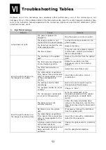
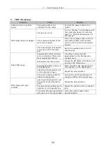
Page 54: ...e correct filter cube The combination of excitation filter barrier filter and dichroic mirror is inappropriate or one of these components is missing Use a filter cube with a correct combination The setting is still for TIRF microscopy Push in the mirror switch lever to change to Epi fl microscopy The eyepiece shutter is not set to Bino Change to Bino Even though the lamp is on the image is not vis...

Page 55: ...ctive No immersion oil has been applied to the tip of an immersion oil type objective Apply Nikon Immersion Oil DF The specified immersion oil is not being used Apply Nikon Immersion Oil DF Viewing is poor The filter cube being used is not suited for the specimen Use a filter cube suited for the specimen The field diaphragm has been stopped down too far Open the field diaphragm so that it is just ...

Page 56: ...r and laser wavelength setting Use filters and wavelength appropriate for the fluorescence reagent used Excessively low laser power Adjust the ND filters of the laser unit and the TIRF attachment Inappropriate filter cube is in the optical path Place the filter cube appropriate to the specimen in the optical path Laser beam focal point is not on the objective s pupil Adjust the laser position Dark...

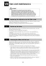
Page 57: ...lit or immediately after it has been turned off When replacing the lamp wait at least 30 minutes after the lamp is turned off 3 Cleaning the filter and the lens Do not let dust fingerprint etc get on the lenses Dirt on the lenses filters etc will adversely affect the view of image Especially in TIRF microscopy if the tip of the objective and the cover glass are dirty it can substantially reduce co...

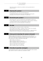
Page 58: ...gent Put the dust proof cover over this product to protect it from dust Before putting on the dust proof cover turn off all power switches of components including the laser flip it to the O side and wait until the lamphouse gets cool sufficiently 7 Moving and relocating the system charged The following tasks should be performed by trained service personnel Any attempt by an unauthorized staff may ...

Page 59: ...cope and accessories 1 Stage ring 26 32 32 is made of glass 1 TIRF2 T FL TIRF2 TIRF100 or TIRF60 EPI40 are interchangeable T FLZA zoom adapter cannot be used 1 Optical fiber C1 single mode fiber Combined with the straight fiber adapter the straight fiber can be used 1 Straight fiber adapter TIRF2 S When connecting a optical fiber that has a straight tip install a straight fiber adapter to the TIRF...

Page 60: ...Spectra physics Head 161C 030 Power supply 263 C04 488nm 10mW C LU2 L1 C LU3 L2 C1 LU3 L1 Blue Manufacturer Coherent Head Sapphire488 20CDRH Power supply CDRH control box 488nm 20mW The laser adapter is required for use C LU2 L1 C LU3 L2 C1 LU3 L1 Manufacturer Crysta Laser Head GCL 025 S Power supply CL 2000 532nm 25mW The laser adapter is required for use C LU2 L2 C LU3 L3 C1 LU3 L2 Manufacturer ...

Page 61: ... Uniphase Head 1125P Power supply 1202 3 100V 1202 1 115V 1202 2 230V 633nm 5mW C LU2 L2 C LU3 L1 C1 LU3 L3 Manufacturer LASOS Head LGK7628 Power supply SAN7460A LGN7460A 633nm 5mW C LU2 L2 C LU3 L1 C1 LU3 L3 Manufacturer Melles Griot Head 05LHP925 Power supply 05LPL915 070 633nm 17mW C LU2 L2 C LU3 L1 C1 LU3 L3 Manufacturer Melles Griot Head 56 ICS 272 Power supply 56 IMA 015 635nm 3mW The laser ...

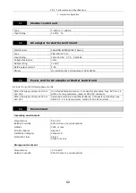
Page 62: ...o use the following power cords When the supply voltage is 100 to 120 VAC UL Listed detachable cord set 3 conductor grounding Type SVT No 18 AWG 3 m long maximum rated at 125 VAC minimum When the supply voltage is 220 to 240 VAC Approved according to EU EN standards 3 conductor grounding Type HO5VV F 3 m long maximum rated at 250 VAC minimum 1 4 Environment Operating environment Temperature 5 to 3...

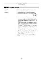
Page 63: ...FCC Rules These limits are designed to provide reasonable protection against harmful interference when the equipment is operated in a commercial environment This equipment generates uses and can radiate radio frequency energy and if not installed and used in accordance with the instruction manual may cause harmful interference to radio communications Operation of this equipment in a residential ar...

Reviews: