OCR Power Supply
External 24V dc supply instructions
–
CIP adapter cable
87
TemBreak
PRO
P_SE-UM-001-EN
– V1.2.0
Action
Note / Illustration
4
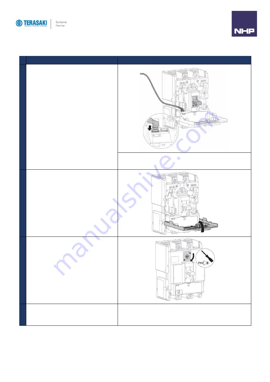
Insert the CIP connector for the CIP adapter in one of
the connectors marked CIP inside the circuit breaker on
the left-hand side.
Route the cable for the CIP adapter along the left-hand
side cable channel of the circuit breaker provided for this
purpose.
Respect the direction of insertion for the connector:
The adapter part marked CIP must be visible from the front. Avoid forcing the
connector when inserting.
5
Close the front cover of the MCCB
6
Using a No.2 Phillips screwdriver, lock the front cover by
rotating the lock clockwise
7
Terminate the other end of the CIP adapter cable to 24V
dc power supply terminals.
Brown wire
+24V dc
White wire
0V dc
Summary of Contents for Terasaki TemBreak PRO P SE Series
Page 106: ...106 TemBreak PRO P_SE UM 001 EN V1 2 0 Annex A Dimensions P160 Dimensions...
Page 107: ...Annex A Dimensions 107 TemBreak PRO P_SE UM 001 EN V1 2 0 P250 Dimensions...
Page 108: ...Annex A Dimensions 108 TemBreak PRO P_SE UM 001 EN V1 2 0 P400 Dimensions...
Page 109: ...Annex A Dimensions 109 TemBreak PRO P_SE UM 001 EN V1 2 0 P630 Dimensions...
Page 111: ...111 TemBreak PRO P_SE UM 001 EN V1 2 0 Annex C I2t Let Through Curves P160_SE...
Page 112: ...Annex C I2t Let Through Curves 112 TemBreak PRO P_SE UM 001 EN V1 2 0 P250_SE...
Page 113: ...Annex C I2t Let Through Curves 113 TemBreak PRO P_SE UM 001 EN V1 2 0 P400_SE...
Page 114: ...Annex C I2t Let Through Curves 114 TemBreak PRO P_SE UM 001 EN V1 2 0 P630_SE...
Page 115: ...115 TemBreak PRO P_SE UM 001 EN V1 2 0 Annex D Peak Let Through Curves P160_SE...
Page 116: ...116 TemBreak PRO P_SE UM 001 EN V1 2 0 P250_SE...
Page 117: ...117 TemBreak PRO P_SE UM 001 EN V1 2 0 P400_SE...
Page 118: ...118 TemBreak PRO P_SE UM 001 EN V1 2 0 P630_SE...
Page 121: ...121 TemBreak PRO P_SE UM 001 EN V1 2 0 This page is intentionally left blank...


