Installation
Alarm, Shunt & UVT Installation
27
TemBreak
PRO
P_SE-UM-001-EN
– V1.2.0
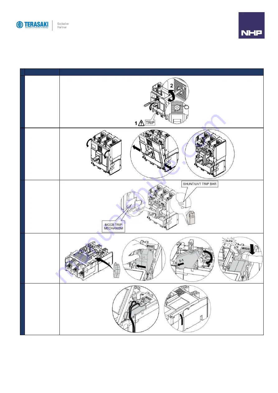
Shunt & UVT installation
Action
Note
1
Switch the Smart
MCCB to the Tripped
Position.
2
Open the front cover of
the MCCB.
3
Locate the shunt or
UVT’s trip bar into the
MCCB trip mechanism
slot.
4
The shunt or UVT will
need to be rolled into
place, follow the
images to the right.
5
Run the wires out the
right-hand side of the
MCCB, through the
allocated groves.
Summary of Contents for Terasaki TemBreak PRO P SE Series
Page 106: ...106 TemBreak PRO P_SE UM 001 EN V1 2 0 Annex A Dimensions P160 Dimensions...
Page 107: ...Annex A Dimensions 107 TemBreak PRO P_SE UM 001 EN V1 2 0 P250 Dimensions...
Page 108: ...Annex A Dimensions 108 TemBreak PRO P_SE UM 001 EN V1 2 0 P400 Dimensions...
Page 109: ...Annex A Dimensions 109 TemBreak PRO P_SE UM 001 EN V1 2 0 P630 Dimensions...
Page 111: ...111 TemBreak PRO P_SE UM 001 EN V1 2 0 Annex C I2t Let Through Curves P160_SE...
Page 112: ...Annex C I2t Let Through Curves 112 TemBreak PRO P_SE UM 001 EN V1 2 0 P250_SE...
Page 113: ...Annex C I2t Let Through Curves 113 TemBreak PRO P_SE UM 001 EN V1 2 0 P400_SE...
Page 114: ...Annex C I2t Let Through Curves 114 TemBreak PRO P_SE UM 001 EN V1 2 0 P630_SE...
Page 115: ...115 TemBreak PRO P_SE UM 001 EN V1 2 0 Annex D Peak Let Through Curves P160_SE...
Page 116: ...116 TemBreak PRO P_SE UM 001 EN V1 2 0 P250_SE...
Page 117: ...117 TemBreak PRO P_SE UM 001 EN V1 2 0 P400_SE...
Page 118: ...118 TemBreak PRO P_SE UM 001 EN V1 2 0 P630_SE...
Page 121: ...121 TemBreak PRO P_SE UM 001 EN V1 2 0 This page is intentionally left blank...


