Installation
Alarm, Shunt & UVT Installation
28
TemBreak
PRO
P_SE-UM-001-EN
– V1.2.0
SMART Auxiliary Installation
The method for installing standard and SMART Auxiliary modules are similar to the Alarm contact modules and clip straight in. Refer to the supplied
Installation Instructions for the respective accessories for further detail.
Action
Note
1
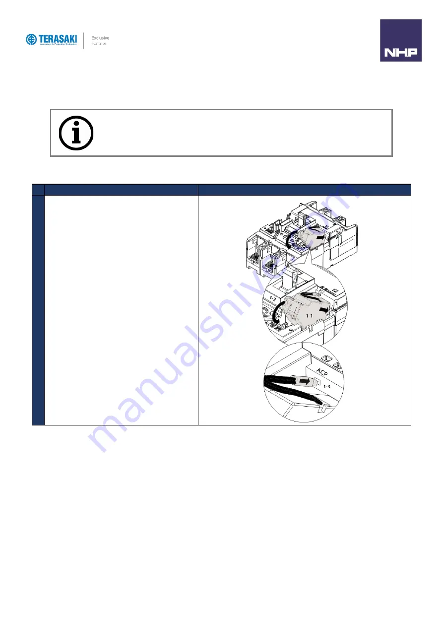
Follow steps 1,2 and 5 of the Alarm Installation Instructions
to access and close the internal accessories chambers and
to run wiring to the Auxiliary.
SMART type AX/AL module is dedicated to the TemBreak
PRO
P_SE MCCB range. It can only be installed in the LH
side accessories chamber as shown.
SMART type AX/AL module must be connected to the ACP
socket inside the MCCB accessory chamber.
Notice
: Install auxiliary units last, to ensure the other accessories can be installed correctly.
Summary of Contents for Terasaki TemBreak PRO P SE Series
Page 106: ...106 TemBreak PRO P_SE UM 001 EN V1 2 0 Annex A Dimensions P160 Dimensions...
Page 107: ...Annex A Dimensions 107 TemBreak PRO P_SE UM 001 EN V1 2 0 P250 Dimensions...
Page 108: ...Annex A Dimensions 108 TemBreak PRO P_SE UM 001 EN V1 2 0 P400 Dimensions...
Page 109: ...Annex A Dimensions 109 TemBreak PRO P_SE UM 001 EN V1 2 0 P630 Dimensions...
Page 111: ...111 TemBreak PRO P_SE UM 001 EN V1 2 0 Annex C I2t Let Through Curves P160_SE...
Page 112: ...Annex C I2t Let Through Curves 112 TemBreak PRO P_SE UM 001 EN V1 2 0 P250_SE...
Page 113: ...Annex C I2t Let Through Curves 113 TemBreak PRO P_SE UM 001 EN V1 2 0 P400_SE...
Page 114: ...Annex C I2t Let Through Curves 114 TemBreak PRO P_SE UM 001 EN V1 2 0 P630_SE...
Page 115: ...115 TemBreak PRO P_SE UM 001 EN V1 2 0 Annex D Peak Let Through Curves P160_SE...
Page 116: ...116 TemBreak PRO P_SE UM 001 EN V1 2 0 P250_SE...
Page 117: ...117 TemBreak PRO P_SE UM 001 EN V1 2 0 P400_SE...
Page 118: ...118 TemBreak PRO P_SE UM 001 EN V1 2 0 P630_SE...
Page 121: ...121 TemBreak PRO P_SE UM 001 EN V1 2 0 This page is intentionally left blank...


