Protection Settings
Long Time Delay (LTD) protection
33
TemBreak
PRO
P_SE-UM-001-EN
– V1.2.0
Thermal memory / Hot
–
Cold start mode
TemBreak
PRO
electronic OCRs have a thermal imaging function, which models the active heating and cooling of electrical conductors as current passes
through them. The thermal imaging function calculates a thermal value
(θ)
for the conductors, which trips the MCCB when its thermal threshold
(θ
trip
) is
reached. This allows the MCCB to simulate the true thermal state of the conductors more accurately, and better protect against overload conditions between
successive operating cycles.
Thermal imaging cannot be disabled in the OCR, however, the P_SE model can be configured with either a hot or cold start mode, which determines
whether the calculated thermal value
θ
is retained if the current drops below the LTD pick-up current threshold
(between 1.05…1.20 x I
r
).
Changes to the Hot
–
Cold start mode can be made using or a combination of the below methods:
-
P_SE OCR embedded display
-
TPED
-
TPCM
P_SE OCR embedded display setting
TPED setting
TPCM setting
Default
COLD:
Cold start mode
HOT:
Hot start mode
“Thermal memory”
OFF:
Cold start mode
ON:
Hot start mode
Command ID: 201
“
LTD Start mode
”
Hex 00 00:
Cold start mode
Hex 00 01:
Hot start mode
Cold start mode
Hot start mode
In Hot start mode, the thermal imaging continues to calculate the thermal value
(θ
H
), even if the current is below the LTD pick-up threshold.
As long as the OCR is powered (self-supply or external backup power), the thermal imaging will continue to function. If power is removed from the OCR,
thermal imaging will continue to operate for at least 20 minutes or until the calculated thermal value
θ
H
reaches 0.
Cold start mode
In Cold start mode, the thermal value (
θ
C
) is only calculated from when the current reaches and exceeds the LTD pick-up current threshold.
If the current drops below the LTD pick-up current threshold, then the thermal value
θ
C
resets to 0.
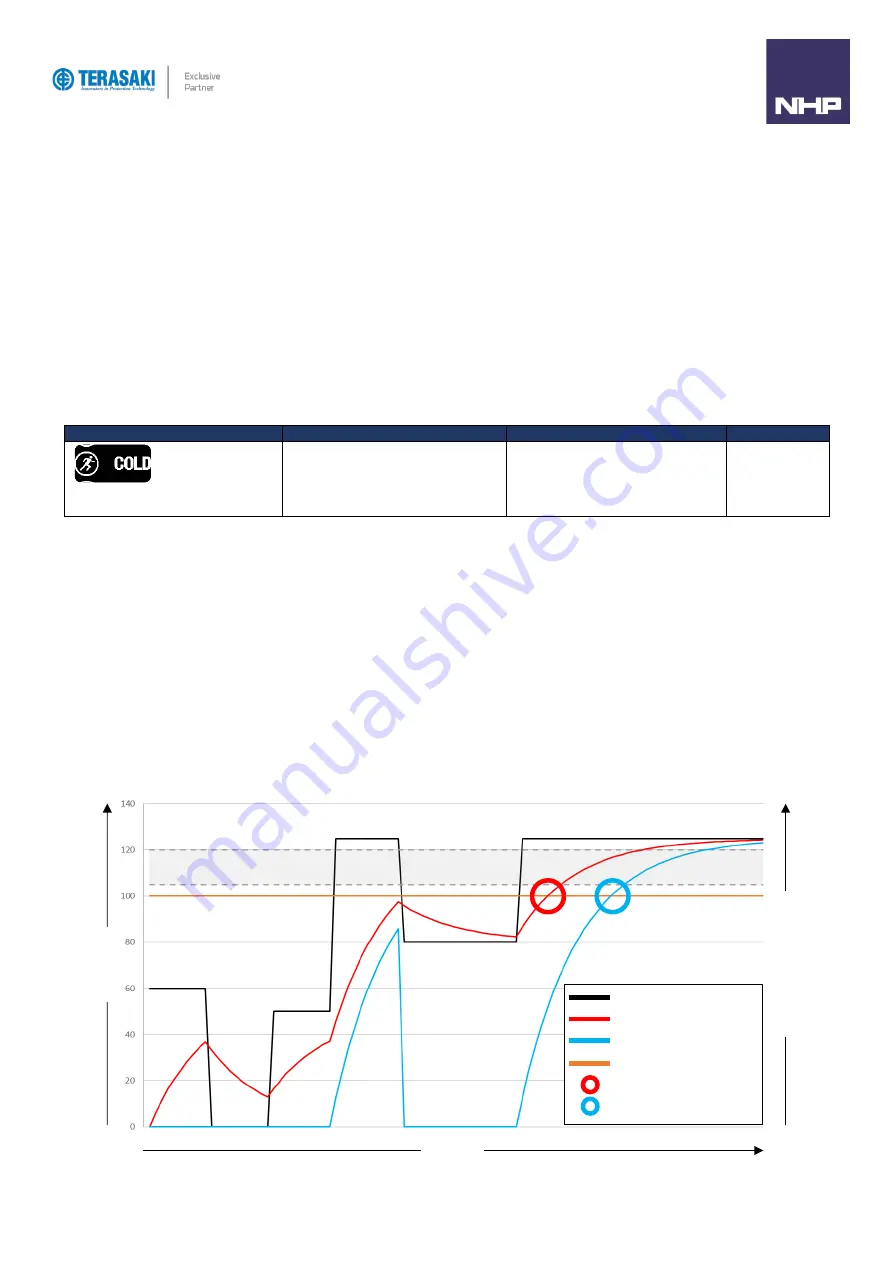
The below figure illustrates the OCR with thermal imaging in both hot and cold start modes. Where the current (I) drops below the LTD pick-up current
threshold
(region in grey between 105…120% of I
r
), the Hot mode thermal value
θ
H
continues to be calculated, whereas the Cold mode thermal value
θ
C
resets to 0 each time. In either start mode, the MCCB trips when the respective thermal value threshold
θ
trip
is reached. The differences between start
modes is made most apparent by the different tripping times after successive operations, where hot mode
θ
H
reaches the tripping threshold
θ
trip
earlier,
providing added safety and optimum protection of the conductors.
LTD pick-up current threshold
(105…120% of I
r)
Current (I
)
Time (t)
The
rma
l Imagi
ng
Va
lue
(
θ
)
Current (I)
Hot mode value (θ
H
)
Cold mode value (θ
C
)
Thermal trip threshold
(θ
trip
)
Hot mode tripping point
Summary of Contents for Terasaki TemBreak PRO P SE Series
Page 106: ...106 TemBreak PRO P_SE UM 001 EN V1 2 0 Annex A Dimensions P160 Dimensions...
Page 107: ...Annex A Dimensions 107 TemBreak PRO P_SE UM 001 EN V1 2 0 P250 Dimensions...
Page 108: ...Annex A Dimensions 108 TemBreak PRO P_SE UM 001 EN V1 2 0 P400 Dimensions...
Page 109: ...Annex A Dimensions 109 TemBreak PRO P_SE UM 001 EN V1 2 0 P630 Dimensions...
Page 111: ...111 TemBreak PRO P_SE UM 001 EN V1 2 0 Annex C I2t Let Through Curves P160_SE...
Page 112: ...Annex C I2t Let Through Curves 112 TemBreak PRO P_SE UM 001 EN V1 2 0 P250_SE...
Page 113: ...Annex C I2t Let Through Curves 113 TemBreak PRO P_SE UM 001 EN V1 2 0 P400_SE...
Page 114: ...Annex C I2t Let Through Curves 114 TemBreak PRO P_SE UM 001 EN V1 2 0 P630_SE...
Page 115: ...115 TemBreak PRO P_SE UM 001 EN V1 2 0 Annex D Peak Let Through Curves P160_SE...
Page 116: ...116 TemBreak PRO P_SE UM 001 EN V1 2 0 P250_SE...
Page 117: ...117 TemBreak PRO P_SE UM 001 EN V1 2 0 P400_SE...
Page 118: ...118 TemBreak PRO P_SE UM 001 EN V1 2 0 P630_SE...
Page 121: ...121 TemBreak PRO P_SE UM 001 EN V1 2 0 This page is intentionally left blank...


