Protection Settings
31
TemBreak
PRO
P_SE-UM-001-EN
– V1.2.0
Adjusting I
r
(Current)
The LTD protection trip range is: 1.05...1.20 x I
r
according to standard AS/NZS IEC 60947.2.
The trip threshold tolerance I
r
for the long-time delay protection is +5% to +20%.
The I
r
trip threshold is firstly set using the I
r
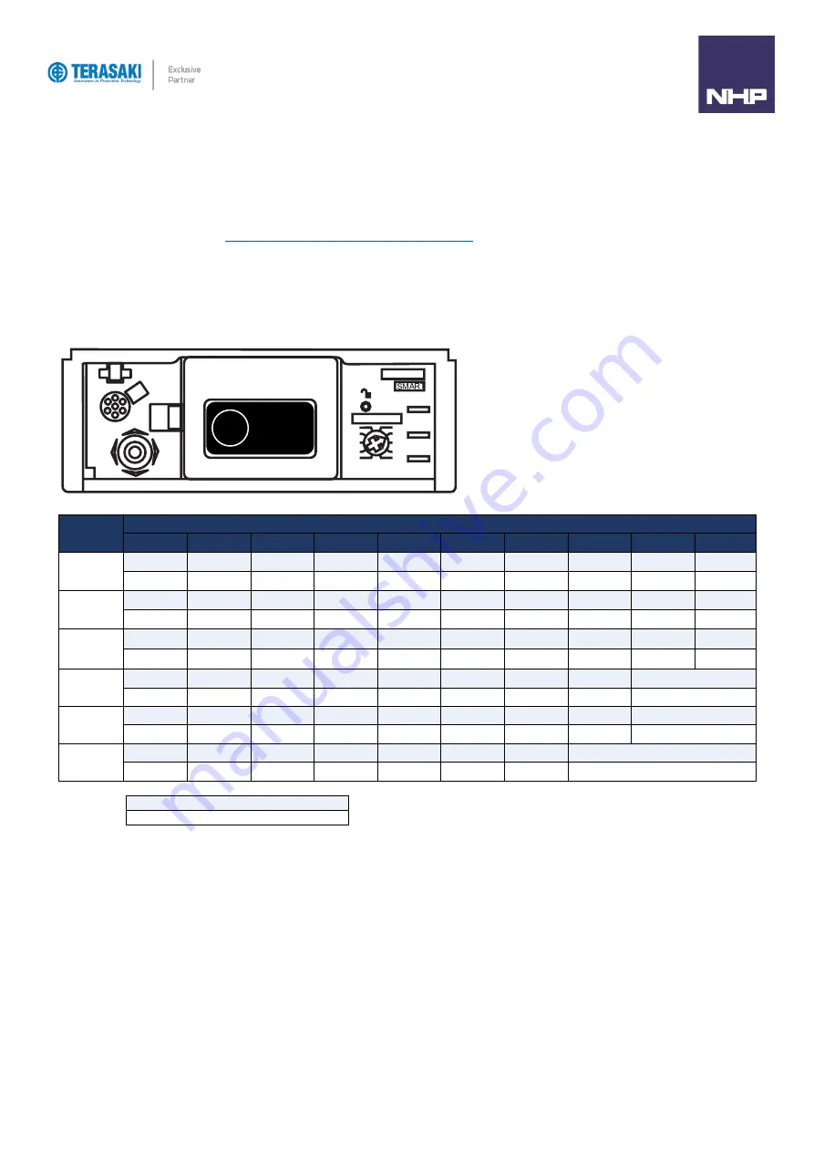
max scale dial on the front of the MCCB, then, if necessary, from the embedded screen display to further adjust
in fine increments of 1A. Refer to the
section for further information on using the I
r
max adjustment
dial and fine adjustments.
Fine adjustments to I
r
parameters can be made using one or combination of the below methods:
-
P_SE OCR embedded display
-
TPED
-
TPCM
Rating (I
n
)
Dial position
1
2
3
4
5
6
7
8
9
10
40A
I
r
max 16
I
r
max 18
I
r
max 20
I
r
max 22
I
r
max 25
I
r
max 28
I
r
max 32
I
r
max 34
I
r1
max 37
I
r1
max 40
16
17
…
18
19
…
20
21
…
22
23
…
25
26
…
28
29
…
32
33
…
34
35
…
37
38
…
40
100A
I
r
max 40
I
r
max 45
I
r
max 50
I
r
max 57
I
r
max 63
I
r
max 72
I
r
max 80
I
r
max 87
I
r1
max 93
I
r1
max 100
40
41
…
45
46
…
50
51
…
57
58
…
63
64
…
72
73
…
80
81
…
87
88
…
93
94
…
100
160A
I
r
max 63
I
r
max 70
I
r
max 80
I
r
max 90
I
r
max 100
I
r
max 110
I
r
max 125
I
r
max 135
I
r1
max 150
I
r1
max 160
63
64
…
70
71
…
80
81
…
90
91
…
100
101
…
110
111
…
125
126
…
135
136
…
150
151
…
160
250A
I
r
max 100
I
r
max 110
I
r
max 125
I
r
max 140
I
r
max 160
I
r
max 180
I
r
max 200
I
r
max 225
I
r1
max 250
100
101
…
110
111
…
125
126
…
140
141
…
160
161
…
180
181
…
200
201
…
225
226
…
250
400A
I
r
max 160
I
r
max 180
I
r
max 200
I
r
max 225
I
r
max 250
I
r
max 300
I
r
max 350
I
r
max 370
I
r1
max 400
160
161
…
180
181
…
200
201
…
225
226
…
250
251
…
300
301
…
350
351
…
370
371
…
400
630A
I
r
max 250
I
r
max 300
I
r
max 350
I
r
max 370
I
r
max 400
I
r
max 500
I
r
max 600
I
r
max 630
250
251
…
300
301
…
350
351
…
370
371
…
400
401
…
500
501
…
600
601
…
630
I
r
max scale setting (A)
I
r
fine adjustment range (A)
100
A
Ir
Summary of Contents for Terasaki TemBreak PRO P SE Series
Page 106: ...106 TemBreak PRO P_SE UM 001 EN V1 2 0 Annex A Dimensions P160 Dimensions...
Page 107: ...Annex A Dimensions 107 TemBreak PRO P_SE UM 001 EN V1 2 0 P250 Dimensions...
Page 108: ...Annex A Dimensions 108 TemBreak PRO P_SE UM 001 EN V1 2 0 P400 Dimensions...
Page 109: ...Annex A Dimensions 109 TemBreak PRO P_SE UM 001 EN V1 2 0 P630 Dimensions...
Page 111: ...111 TemBreak PRO P_SE UM 001 EN V1 2 0 Annex C I2t Let Through Curves P160_SE...
Page 112: ...Annex C I2t Let Through Curves 112 TemBreak PRO P_SE UM 001 EN V1 2 0 P250_SE...
Page 113: ...Annex C I2t Let Through Curves 113 TemBreak PRO P_SE UM 001 EN V1 2 0 P400_SE...
Page 114: ...Annex C I2t Let Through Curves 114 TemBreak PRO P_SE UM 001 EN V1 2 0 P630_SE...
Page 115: ...115 TemBreak PRO P_SE UM 001 EN V1 2 0 Annex D Peak Let Through Curves P160_SE...
Page 116: ...116 TemBreak PRO P_SE UM 001 EN V1 2 0 P250_SE...
Page 117: ...117 TemBreak PRO P_SE UM 001 EN V1 2 0 P400_SE...
Page 118: ...118 TemBreak PRO P_SE UM 001 EN V1 2 0 P630_SE...
Page 121: ...121 TemBreak PRO P_SE UM 001 EN V1 2 0 This page is intentionally left blank...


