Instruction Manual
MN013017EN
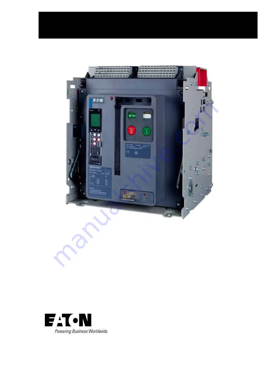
IZM32 / IN32 low voltage air circuit breaker
IZM32 / IN32
May 2022
Page 1: ...Instruction Manual MN013017EN IZM32 IN32 low voltage air circuit breaker IZM32 IN32 May 2022...
Page 2: ...are covered in individual instruction leaflets specific to the accessory This information is also available from the Eaton Web site at www eaton com For application information consult Eaton or see ap...
Page 3: ...dary jumpers 5 2 7 Installing drawout circuit breaker 6 2 7 1 Circuit breaker positioning 6 2 7 2 Levering circuit breaker 8 2 8 Fixed circuit breaker 11 2 9 Circuit breaker operation 11 2 10 Technica...
Page 4: ...ES 34 SECTION 6 WIRING DIAGRAMS 44 SECTION 7 INSPECTION AND MAINTENANCE 51 7 1 General 51 7 2 General cleaning recommendations 51 7 3 When to inspect 51 7 4 What to inspect 51 7 4 1 Functional field t...
Page 5: ...ign using an electronic tripping system It is designed and tested for use at nominal voltages of AC380 415V 440V and 500 690V IZM32 IN32 circuit breakers are available with continuous current ratings...
Page 6: ...t its operation and the associated hazards should be permitted to work on the equipment Additionally only qualified personnel should be permitted to install or operate the equipment 2 Always be certai...
Page 7: ...ing until the breakers are ready for inspection testing and or installation When ready to inspect and install the circuit breaker carefully remove the banding straps and lift off the cardboard box Rem...
Page 8: ...der the integral molded lifting handles on both sides of the circuit breaker Every effort should be made during lifting to minimize circuit breaker swing and tilt If the circuit breaker is to be lifte...
Page 9: ...interlocks Doing so and using a lower capacity circuit breaker in an incompatible cassette could result in an electrical fault that could result in death bodily injury and or equipment damage Molded...
Page 10: ...ails Be certain that the circuit breaker s four molded drawout rail supports are fully seated in the extension rail cutouts on both sides Figure 2 3 Do not remove the lifting yoke from the circuit bre...
Page 11: ...y Connections Not Made Only Ground Connection Made Breaker Still Behind Door Typical Storage Position Circuit Breaker Side View Compartment Front Door Secondary Connection Made Rear of Compartment Pri...
Page 12: ...e and ratchet which is not provided Figure 2 9 As long as the levering access door is raised the circuit breaker is held trip free Begin by rotating the levering in screw to the full counterclockwise...
Page 13: ...it breaker including automatic primary and secondary connections Horizontal stabs and horizontal customer busbar terminals are available as standard Figure 2 11 The cassette terminal connections can b...
Page 14: ...2 11 Drawout cassette features front and rear views 2 1 4 3 6 5 8 7 1 1 2 2 3 4 5 6 6 7 7 8 9 9 9 10 10 10 4 Front View Rear View Extension Rails Extension Rail Cutout Secondary Plug in Connectors Se...
Page 15: ...circuit breaker s type secondary connector Both secondary connection devices are mounted at the top front of the circuit breaker The fixed circuit breaker frame has two mounting feet one on each side...
Page 16: ...may be required or the breaker may have to be de rated Refer to the table Rated currents of the circuit breakers at different ambient temperature presented in this section for de rating information at...
Page 17: ...res Altitude derating factors Notes IZM series circuit breakers can be applied at their full voltage and current ratings up to a maximum altitude of 2000 meters above sea level When installed at highe...
Page 18: ...intended to provide a guideline for the installation of fixed type or drawout type circuit breakers in an enclosure The diagram and related dimensions can be used for reference Electrical clearance d...
Page 19: ...ont and rear views Section 3 Circuit breaker description and operation 3 1 Introduction IZM32 IN32 circuit breakers are available in two physical frame sizes 3 4 poles in both drawout and fixed mounti...
Page 20: ...6 2 5 9 10 5 2 1 4 3 6 7 8 9 10 Fixed primary terminal with optional vertical adapter Arc chamber Mounting foot Circuit breaker nameplate Tripper bar Baffled arc chute cover Secondary disconnect Facep...
Page 21: ...cessory windows Trip unit Contact status open close Spring status charged discharged Manual OFF button push Manual ON button push Manual charge handle Optional operation counter Padlockable levering d...
Page 22: ...case and is electrically isolated and insulated from current contact structures It is covered by an insulating front cover 3 3 Operating mechanism The IZM32 IN32 operating mechanism is based on the pr...
Page 23: ...to the corresponding instructions leaflet An electrical motor operator that is used to charge the closing spring automatically can be added to a manually operated circuit breaker in the field Figure 3...
Page 24: ...XR 25 LSIG protection Yes Yes Disable I Yes Yes GF protection Option Option GF alarm Option Option Display Yes Yes Programmable No No Current metering Yes Yes Power energy metering No Yes Power qualit...
Page 25: ...In rating of the breaker while the value on the battery cover is for reference only when the LCD is not powered The In rat ing displayed on the LCD screen and In rating printed on the frame rating mo...
Page 26: ...ination on each contact 5 Contact blocks are individually mounted and hence contact positions may be empty depending on accessories and options ordered 6 The tension clamp terminals will support solid...
Page 27: ...ge air circuit breaker MN013017EN May 2022 www eaton com Section 4 Dimensional drawings IZM32 Fixed Type Dimensions and Horizontal Board Dimensions 3P 800 3200A Front view Right view Top view Section...
Page 28: ...2 IN32 low voltage air circuit breaker MN013017EN May 2022 www eaton com Section 4 Dimensional drawings IZM32 Fixed Type Dimensions and Horizontal Board Dimensions 4P 800 3200A Front view Right view T...
Page 29: ...N May 2022 www eaton com Section 4 Dimensional drawings IZM32 Fixed Type Panel Cutout and External Vertical Board Dimensions 3P and 4P 800 1600A Max distance to isolation surface Door cut out Door cut...
Page 30: ...r MN013017EN May 2022 www eaton com Section 4 Dimensional drawings IZM32 Fixed Type External Vertical Board Dimensions 3P and 4P 2000A Door cut out Door cut out Door panel mounting hole Door panel mou...
Page 31: ...N013017EN May 2022 www eaton com Section 4 Dimensional drawings IZM32 Fixed Type External Vertical Board Dimensions 3P and 4P 2500 3200A Door cut out Door cut out Door panel mounting hole Door panel m...
Page 32: ...low voltage air circuit breaker MN013017EN May 2022 www eaton com Section 4 Dimensional drawings ZM32 Withdrawable Type Dimensions 3P and 4P 800 3200A Notes Drawer switch position Recommended minimum...
Page 33: ...10 11 50 292 10 Note 1 Mperial dimensions are Inches on top metric dimensions are mm bottom 2 All dimensions are reference only 3 Tolerance range is shown as follow Connected position Test position W...
Page 34: ...Bottom view 2 places 2 places 12 places 4 places 4 places 2 places 4 places 4 places 3 places 4 pole mounting locations 3 pole mounting locations Earth contact access hole Rear view Bottom view Rear v...
Page 35: ...2 4 25 4 25 4 231 9 Mounting plane 41 6 475 5 152 4 384 2 88 9 88 9 152 4 37 6 10 2 Optional earth bus mounting location replace existing bolts with M8x25 hex bolts for use with 1 4 6mm bus Required m...
Page 36: ...ker MN013017EN May 2022 www eaton com Section 4 Dimensional drawings IZM32 Withdrawable Type Cassette Horizontal Board Wiring Dimensions 3P and 4P 800 3200A 16 33 5 37 1 127 127 50 8 101 6 11 2 117 50...
Page 37: ...eaton com Section 4 Dimensional drawings IZM32 Withdrawable Type Cassette Vertical Board Wiring Dimensions 3P and 4P 4000A 127 127 30 5 30 5 123 161 83 3 46 101 6 431 411 101 6 400 57 2 10 9 486 127 1...
Page 38: ...04 05 06 07 08 09 1 2 3 4 5 6 7 8 9 1 2 3 4 5 6 7 8 9 10 20 30 40 50 60 70 80 90 100 1 2 3 4 5 6 7 8 9 10 20 30 40 50 60 70 80 90 100 200 300 400 500 600 700 800 900 1000 2000 3000 4000 5000 6000 7000...
Page 39: ...1 0 3 0 4 1 3 0 5 Time in Seconds Current in Multiples of Long Delay Pickup Ir Notes 1 This curve shown as a multiple of the LONG PU setting Ir The actual pickup point occurs at 110 of the Ir with 5 t...
Page 40: ...determined by the interrupting rating of the circuit breaker 6 Curves applies from 20 C to 70 C ambient Temperatures above 85 C will cause over temperature trip 7 This curve is for 50Hz 60Hz applicati...
Page 41: ...ion 2 The peak current level setting for IZM63 is xed at 176kA 4 The PXR will light the Instantaneous LED for a High Instantaneous trip 5 The total Instantaneous clearing times shown are conservative...
Page 42: ...rmined by the interrupting rating of the circuit breaker 6 Curves applies from 20 C to 70 C ambient Temperatures above 85 C will cause over temperature trip 7 This curve is for 50Hz 60Hz applications...
Page 43: ...t Rating In 6 The end of the curve is determined by the interrupting rating of the circuit breaker 7 Curves applies from 20 C to 50 C ambient Temperatures above 85 C will cause over temperature trip 8...
Page 44: ...t be ENABLED via setting Maintenance Mode switch to ON position remote switch or communications for these curves to apply Maintenance Mode is in use being shown by blue LED 4 The PXR will light the In...
Page 45: ...ance 2 SDPU 1 5x to 10x of Ir have 100 10 tolerance 3 LD Time 0 5s to 24s have 100 0 30 tolerance 4 SD Slope I T The short pickup points have 10 tolerance time setting from 0 1s to 0 5s with steps of...
Page 46: ...nce time setting from 0 1s to 0 5s with steps of 0 1s except 0 2s tolerance is 100 0 30 except 0 1s has tolerance 100 0 40 5 I r response time value projected to I T line will determine the other brea...
Page 47: ...This curve shown as a multiple of the LONG PU setting Ir The actual pickup point occurs at 110 of the Ir with 5 tolerance 2 SDPU 1 5x to 10x of Ir have 100 10 tolerance 3 LD Time 0 5s to 24s have 100...
Page 48: ...On a 4P circuit breaker the neutral current sensor has the same style and wiring method as the phase sensor located within the circuit breaker frame no need to connect the secondary terminals 11N1 12N...
Page 49: ...he Spring Release internal electronics pulse the SR coil and then provides a high impedance circuit This provides anti pumping 4 When the spring discharges its energy the motor switch will re energize...
Page 50: ...voltage air circuit breaker MN013017EN May 2022 www eaton com Section 6 Wiring diagrams Under voltage release IZM series circuit breaker Monitored Voltage 94 93 Notes 1 Treated as the positive voltag...
Page 51: ...Remote Indication Maintenance Mode indication Contact rating 1 A 120 Vac 1 A 24 Vdc and 0 5 A 230 Vac 2 For the PXR20 25 the Alarm 2 is for High Load alarm Ground Fault alarm Contact rating 1 A 120 Va...
Page 52: ...ximum length of this wiring to remotely arm the switch or alternate relay contact is 63 78 feet 3 m Use 20 AWG wire or larger 4 A remote Stack Light Annunciator panel or other remote indication device...
Page 53: ...LB LC PT MODULE BREAKER A 0 600 L L INPUT B C To additional breakers 16 max Secondary Contacts 1 N 3 5 30 PTVB 29 PTVA 31 PTVC TP2 32 PTVN LN LA LB LC PT MODULE BREAKER A 0 600 L L INPUT B C To additi...
Page 54: ...3 Notes 1 Twisted together AWG 14 to 20 copper wire Route the Zone Interlock wiring separate from power conductors DO NOT GROUND any Zone Interlock wiring 2 The maximum distance between two farthest b...
Page 55: ...ts can be driven into areas such as the breaker mechanism where additional friction sources could create problems Never use a wire brush to clean any part of the circuit breaker 7 3 When to inspect Do...
Page 56: ...lace the accessory s function Charge the breaker mechanism springs either using the charging handle or the motor operator Close the breaker by applying rated voltage to the spring release accessory an...
Page 57: ...d by looking directly down into the arc chamber Figure 7 3 and Figure 7 4 A contact wear indicator is provided for each primary contact and indicates whether or not the contact should be replaced Insp...
Page 58: ...act wear indicator with circuit breaker closed Side to Side Ledge Side to Side Ledge Contact Wear Inspection Area ledge not visible under contacts Contact Wear Inspection Area ledge now becoming visib...
Page 59: ...nter Circuit breaker makes no attempt to close with either local manual or remote controls springs do not discharge Closing spring not fully charged check SPRING CHARGED indicator Charge spring manual...
Page 60: ...S WARRANTIES EXPRESSED OR IMPLIED INCLUDING WARRANTIES OF FITNESS FOR A PARTICULAR PURPOSE OR MERCHANTABILITY OTHER THAN THOSE SPECIFICALLY SET OUT IN ANY EXISTING CONTRACT BETWEEN THE PARTIES ANY SUC...