background image

I.B. 3A74499B

Effective 11/97  Supersedes.B. 3A74499A Dated May, 1993

Cutler-Hammer

Instructions for Installation, Operation and Maintenance 
of Type W-VAC Vacuum Circuit Breakers

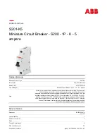
W-VAC Breaker Element

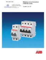
W-VAC Breaker with Carriage
Assembly for SIngle Tier Switchgear

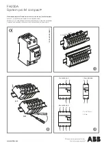
W-VAC Breaker with Cradle 
Assembly for Double Tier Switchgear

Summary of Contents for 36W-VAC25

Page 1: ...1993 Cutler Hammer Instructions for Installation Operation and Maintenance of Type W VAC Vacuum Circuit Breakers W VAC Breaker Element W VAC Breaker with Carriage Assembly for SIngle Tier Switchgear W...

Page 2: ......

Page 3: ...LD BE ATTEMPTED ONLY BY QUALIFIED PERSONNEL THIS INSTRUCTION BOOK SHOULD NOT BE CON SIDERED ALL INCLUSIVE REGARDING INSTALLA TION OR MAINTENANCE PROCEDURES IF FUR THER INFORMATION IS REQUIRED YOU SHOU...

Page 4: ...t Interface Check 13 SECTION 5 DESCRIPTION AND OPERATION 5 1 Interrupter Assembly 16 5 1 1 Vacuum Interrupter 16 5 1 2 Contact Erosion Indicator 17 5 1 3 T Cutout Loading Spring Indicator 17 5 1 4 Con...

Page 5: ...Warning 25 6 2 Frequency 25 6 3 Inspection and Maintenance Procedures 26 6 4 Vacuum Interrupter Integrity Test 27 6 5 Contact Erosion and Wipe 27 6 6 Insulation 28 6 7 Insulation Integrity Check 28 6...

Page 6: ...reaker Manual Operation Single Tier Breaker Shown 13 5 1 Flush Mounted Configuration 16 5 2 Behind the Door Configuration 17 5 3 Closeup of Type W VAC Breaker Vacuum Interrupters and Current Carrying...

Page 7: ...W VAC BREAKERS ARE PROTECTIVE DEVICES AS SUCH THEY ARE MAXIMUM RATED DEVICES THEREFORE THEY SHOULD NOT UNDER ANY CIRCUMSTANCES BE APPLIED OUT SIDE THEIR NAMEPLATE RATINGS WARNING Table 1 1 Type W VAC...

Page 8: ...he hf 3L h3Le he hf S hS L h W he Y h Y J h U he hf H h V he hf he N he hf 3 hf J he W he V4 L h U he hf N h V he3L hf H h S hf J he W he Y L h U hf N h V he hf H h hf L h X he X hf J h N1 heV H h N...

Page 9: ...V M 5 7 V H e hf 3L e N V h Xg X h X X h V h V e N1 hS N1 h L Lh7H h X f31 X T5 Xe Xe J5 Xe X h he X e e e e fS5 V Y V eV g U hf e f g f V f V hJ 1 h N1 h H f Y V h7 h J h h 3L f hf h Lhe S J h3 V h 7...

Page 10: ...not work on a breaker with the secondary test cou pler engaged Failure to disconnect the test coupler could result in an electrical shock leading to death per sonal injury or property damage Do not wo...

Page 11: ...for any signs of damage or rough handing Open the con tainer carefully to avoid any damage to the contents When opening the container be careful that any loose items or hardware are not discarded with...

Page 12: ...cks should be made to make sure that the breaker is free from shipping dam age and is in satisfactory operating condition The breaker is shipped with its contacts open and clos ing springs discharged...

Page 13: ...97 Figure 3 2 Type W VAC breaker element faceplate 1 2 3 8 7 4 5 6 Front Panel Manual Charge Socket Open Closed Indicator Spring Charged Discharged Indicator Operation Counter Rating Nameplate Manual...

Page 14: ...1 2 3 4 5 L H Closing Spring Anti pump Relay Auxiliary Switch Motor Cutoff Switch Closing Cam Spring Release Close Coil Assembly Shunt Trip Assembly Position Switch Charging Motor Charging Pawl Ratch...

Page 15: ...4 Rear external view of W VAC breaker element 1 Secondary Disconnect Lifter Yoke Opening Support Insulator Primary Disconnect Vacuum Interrupter Contact Loading Spring Wipe Spring Operating Rod Drive...

Page 16: ...view W VAC breaker with carriage assembly for single tier switchgear Side View Rear View Mechanism Enclosure Support Insulator Primary Disconnect Levering in Screw Carriage Carriage Wheel Shoot Bolt...

Page 17: ...VAC breaker with cradle assembly for double tier switchgear Front View Rear View Mechanism Enclosure Support Insulator Primary Disconnect Levering in Screw Cradle Cradle Wheel Shutter Operator Leveri...

Page 18: ...TACT EROSION AND WIPE Manually charge the closing springs and close the breaker Check contact erosion and wipe as described in Section 6 5 4 6 PRIMARY CIRCUIT RESISTANCE Check the primary circuit resi...

Page 19: ...Type W VAC breaker manual operation single tier breaker shown a Inserting the maintenance tool into the manual charging socket b Lifting shoot lever permits insertion of levering crank c Manually clos...

Page 20: ...Anti Close Interlock This interlock prevents releasing the closing springs electrically or manually if the breaker is already closed d Anti Latch Interlock This interlock prevents the breaker from bei...

Page 21: ...sembly version lift the shoot bolt lever and pull the breaker out The breaker will close and trip as it comes out from the Test position 2 For the double tier configuration cradle assembly version ret...

Page 22: ...is racked into the fully connected position Possibility 3 The basic breaker element combined with a cradle assembly is used for double tier switchgear This combination is only for use in a behind the...

Page 23: ...is located on the moving stem of the interrupter Figures 6 2 and 6 3 In order to determine if the contacts have eroded to the extent that the interrupter must be replaced close the breaker and observ...

Page 24: ...ed to the support molding resulting in the support molding being enclosed on all four vertical sides Figure 5 4 5 2 STORED ENERGY MECHANISM KEEP HANDS AND FINGERS AWAY FROM THE BREAKER S INTERNAL PART...

Page 25: ...gh the main link to close the breaker In Figure 5 5c the linkage is shown with the breaker in the closed position before the closing springs have been recharged Interference of the trip D shaft with t...

Page 26: ...T XV X W T h V XV T R Ug N L N R XV U N1g W 3L X V S X Y V I 3 eW R h eV4 UeW g W XfV 7H 0R T T KS5 g 0R R40Y e 6T e W eI Y O g W Yh 0Y 7H hfV L g 3L f Kh V X S 3 O e eV X f he Y e V40Y h3Le S e f e h...

Page 27: ...e V h g f e e V e e g hf f e e e e f W hf e f Y e e f J5 W2 Y h Xe f fW2 e U heV Me V e hf f g f W g W hO U he f Y f 0Y V g T e f f e eV U O K W V g 0R4 e f Y J5 Y X X V X e f f g J LV f X S Xh e e T...

Page 28: ...nted male plugs To disengage the sec ondary plugs from the TEST position simply push the carriage to the rear 5 3 3 UNDERVOLTAGE TRIP DEVICE The undervoltage trip device for W VAC breakers is an elect...

Page 29: ...d by the breaker operating shaft prevents the levering crank from being inserted with the breaker in the Closed position 5 4 3 ANTI CLOSE INTERLOCK This interlock prevents releasing the closing spring...

Page 30: ...6Xg gW 6K f e W 1 6K f gW2 6Kg g O2 6X W2 6Kg f W2 X W26Kg Lg O2 6X gO2 6X N N X W 6K H 3 X J L W2 5 W2 6X 7 W2 W26X 3 K e f O 5 X f f W H 6X eJ eW 5 6X e Lf O f f O2 1 7 6Xf fW 1 7 6XfJ 1f W2 1 W2 6X...

Page 31: ...he g V he 3T5 f Y eS 0 Me Hhe X 3T Xh N H g W 7UfV U O he h V e W V X g g U V U he U N R g 3L g N1 S he h X e V h N1 g U he g S g g S1 he Y e W g he h 7H g f 3Lhe g f h 3L hf eV he h 3L X V hf 3T X he...

Page 32: ...7H 7 L heS5 75 7H V f 3 h X he f N1 e R4 g S S g He hV g O he X f gV g 7H e 5 X e S S g g L e V X U he fO2 f X V h 3L 3Lg he Ke X f e e7He U g W e f h U he S f h f e V Xe 7H 7 heW e 31 1 Le N1 heN1 31...

Page 33: ...free cloth Primary Disconnects No burning or damage Visual Check Replace if burned damaged or eroded 3 Control Closing and Tripping Device Smooth and correct Test closing and tripping Replace any defe...

Page 34: ...uld have sufficient volt ampere capacity It is recommended that the equipment be capable of delivering 25 milliamperes for one minute Although an ac high potential test is recommended a dc test may be...

Page 35: ...55812CA or commercial equivalent Secondary control wiring requires inspection for tightness of all connections and damage to insulation 6 7 INSULATION INTEGRITY CHECK Primary Circuit The integrity of...

Page 36: ...c These bearings are packed at the factory with a top grade slow oxidizing grease which normally should be effective for many years They should not be disturbed unless there is definite evidence of sl...

Page 37: ...ood grease solvent Don not use carbon tetracholride They should then be washed in light machine oil until the cleaner is removed After the oil has been drawn off the bearings should be packed with Cut...

Page 38: ...itch off Secondary Disconnects Motor Cut off Switch Poor or burned contacts Lever not operational Terminals and connectors Poor or burned contacts Motor Brushes worn or commutator segment open Mechani...

Page 39: ...ch or trip bar not reset Auxiliary Switch b contact open or burned Motor Cut off Contacts open or burned Trip Coil Assembly Clapper fails to reset Pole Shaft Not open fully Trip Latch Reset Spring Dam...

Page 40: ...en Terminals and Connections Poor or burned or open Trip Mechanism Trip Clapper Jammed Trip Bar Trip Latch Jammed Trip Sound Trip Mechanism Pole Shaft Jammed Operating Rod Assembly Broken or pins out...

Page 41: ...and con tinuity requirements Each customer should develop his own stock level based on operating experience Refer to Table 7 1 for guidance 7 2 ORDERING INSTRUCTIONS a Always specify the breaker rati...

Page 42: ...W M I MI Y hg Y X hf h 31 hf g V hf 3 6T KO2 W26Xhe S 40R4 U 0R X h 6T T W Yf B 9e h X S U 7U T K C MB hf V4 0R R N U H f g U S 6T T2 h J R MI R R he Y V Yh g h hf h hf h hf h hf h hf h h h e f h M h...

Page 43: ...125 VAC Cap trip 3759A76G02 1 220 250 VDC 220 250 VAC Cap trip 3759A76G03 1 15 UV Trip Coils 48 VDC 8067A19G01 1 110 125 VDC 8067A19G02 1 220 250 VDC 8067A19G03 1 16 Motor Cut Off Switch 5677B02G01 1...

Page 44: ...ard 691C662G01 1 UV 691C666G01 1 21 Trip Latch Hatchet 699B040G01 1 22 Cluster Assembly 630A 699B104G01 1 800 1250A 508B022G01 1 1600 2000A 5677B328G01 1 23 Shock Absorber 5677B26H01 1 W f hf e h 6K W...

Page 45: ...I B 3A74499B Page 39 Effective 11 97...

Page 46: ...I B 3A74499B Page 40 Effective 11 97...

Page 47: ...I B 3A74499B Page 41 Effective 11 97...

Page 48: ...e contract between the purchaser and Cutler Hammer NO WARRANTIES EXPRESSED OR IMPLIED INCLUDING WARRANTIES OF FITNESS FOR A PAR TICULAR PURPOSE OR MERCHANTABILITY OR WARRANTIES ARISING FROM COURSE OF...

Reviews: