Calculating the Analog Voltage Output
Service Manual
10030881 Rev. B 12-2008
95
hold
s
that point for 15 seconds. It increases to 1.0 VDC and hold
s
that value for 15
seconds. The third part of the calibration signal is a stair step signal. The stair step
signal, begins at 0.0 VDC and increases up to 1.0 VDC in 0.1 VDC increments, each
held for one (1) second. Select the 0.0 VDC, 1.0 VDC, or stair step signal individually,
using the ANALOG softkey menu option.
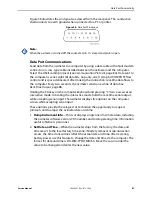
The OxiMax N-600x pulse oximeter data port provides analog voltage outputs
between pins 6, 13, 14, and ground (pin 10), which can be used to calibrate oximeters
such as a chart recorder. The voltage represents a specific measured parameter's
current value. The voltage differential varies proportionally from 0.0 to +1.0 VDC as
the pin's parameter varies over its full range of values. For example, as the current
value of SpO
2
varies from 0% to 100%, the voltage from pin 6 to ground (pin 10) varies
from 0.0 to +1.0 VDC. A voltage of 0.94 volts indicates a current SpO
2
value of 94.
Figure 60.
Data Port Pin Layout
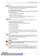
To set analog voltage output
1. Press the SETUP softkey.
2. Press the NEXT softkey three times.
3. Press the ANALOG softkey.
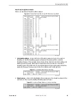
Figure 61.
Analog Voltage Screen
a.
VOLT
Options
—Selecting the 0 VOLT or 1 VOLT softkey causes that voltage to appear
at pins 6, 13, or 14 as referenced to ground pins 5 and 10.
b.
STEP Option
—Selecting the STEP softkey causes the voltage to increase from 0.0 to
1.0 volts at 1/10th-volt increments, with each step lasting at least one second.
4. Press the BACK softkey.
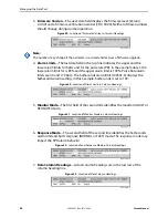
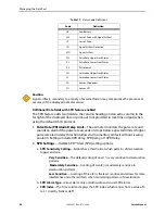
Figure 59.
Analog Pinouts
Pin
VDC
Parameter
Parameter Range
6
Saturation
0 - 100%
13
Pulse Rate
0 - 250 bpm
14
Waveform
0 - 254 PAU
Summary of Contents for OXIMAX N-600X Series
Page 8: ...viii 10030881 Rev B 12 2008 Service Manual...
Page 12: ...Safety Information 12 10030881 Rev B 12 2008 Service Manual...
Page 44: ...Theory of Operations 44 10030881 Rev B 12 2008 Service Manual...
Page 96: ...Managing the Data Port 96 10030881 Rev B 12 2008 Service Manual...
Page 188: ...Oximeter Schematics 188 10030881 Rev B 12 2008 Service Manual Main PCB Schematic Sheet 1 of 13...
Page 189: ...Service Manual 10030881 Rev B 12 2008 189 Main PCB Schematic Sheet 2 of 13...
Page 191: ...Service Manual 10030881 Rev B 12 2008 191 Main PCB Schematic Sheet 4 of 13...
Page 192: ...Oximeter Schematics 192 10030881 Rev B 12 2008 Service Manual Main PCB Schematic Sheet 5 of 13...
Page 194: ...Oximeter Schematics 194 10030881 Rev B 12 2008 Service Manual Main PCB Schematic Sheet 7 of 13...
Page 195: ...Service Manual 10030881 Rev B 12 2008 195 Main PCB Schematic Sheet 8 of 13...
Page 197: ...Service Manual 10030881 Rev B 12 2008 197 Main PCB Schematic Sheet 10 of 13...
Page 200: ...Service Manual 10030881 Rev B 12 2008 200 Main PCB Schematic Sheet 13 of 13...
Page 201: ...Service Manual 10030881 Rev B 12 2008 201 Main PCB Assembly Drawing Front View...
Page 204: ...Oximeter Schematics 204 10030881 Rev B 12 2008 Service Manual...
Page 209: ......

