


Operating the Oximeter
78
10030881 Rev. B 12-2008
Service Manual
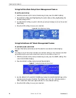
Using the Pulse Rate Delay Alarm Management Feature
To set the alarm delay
1. With the oximeter in the normal monitoring mode, press the LIMITS softkey.
2. Press SELECT softkey until highlighting the alarm delay setting, highlighting the
default setting of OFF.
3. Use the ADJUST UP key to select a five (5) second alarm delay or a ten (10) second
alarm delay.
4. Press the EXIT softkey to save your selection.
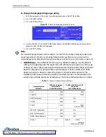
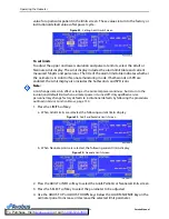
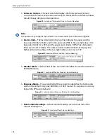
Figure 36.
Pulse Rate Delay Setting
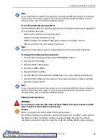
Using the SatSeconds™ Alarm Management Feature
To set SatSeconds alarm limit
To adjust the SatSeconds limit, select the adult or neonate alarm limit display.
Note:
The ability to adjust the SatSeconds Alarm limit default settings can be enabled or disabled
by qualified service personnel as described in
1. With the oximeter in the normal monitoring mode, press the LIMITS softkey. The
current alarm limits display.
2. Press the SELECT softkey twice to select %SpO
2
SAT-S.
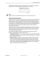
Figure 37.
Setting the SatSeconds Alarm Limit
3. Use the ADJUST UP or ADJUST DOWN keys below the ALARM SILENCE key on the
oximeter panel to select the limit. The choices are 10, 25, 50, 100 SatSeconds or
OFF. A decimal to the lower right indicates it is not a default setting.
4. Press the EXIT softkey to save your selection.
Summary of Contents for OXIMAX N-600X Series
Page 8: ...viii 10030881 Rev B 12 2008 Service Manual...
Page 12: ...Safety Information 12 10030881 Rev B 12 2008 Service Manual...
Page 44: ...Theory of Operations 44 10030881 Rev B 12 2008 Service Manual...
Page 96: ...Managing the Data Port 96 10030881 Rev B 12 2008 Service Manual...
Page 188: ...Oximeter Schematics 188 10030881 Rev B 12 2008 Service Manual Main PCB Schematic Sheet 1 of 13...
Page 189: ...Service Manual 10030881 Rev B 12 2008 189 Main PCB Schematic Sheet 2 of 13...
Page 191: ...Service Manual 10030881 Rev B 12 2008 191 Main PCB Schematic Sheet 4 of 13...
Page 192: ...Oximeter Schematics 192 10030881 Rev B 12 2008 Service Manual Main PCB Schematic Sheet 5 of 13...
Page 194: ...Oximeter Schematics 194 10030881 Rev B 12 2008 Service Manual Main PCB Schematic Sheet 7 of 13...
Page 195: ...Service Manual 10030881 Rev B 12 2008 195 Main PCB Schematic Sheet 8 of 13...
Page 197: ...Service Manual 10030881 Rev B 12 2008 197 Main PCB Schematic Sheet 10 of 13...
Page 200: ...Service Manual 10030881 Rev B 12 2008 200 Main PCB Schematic Sheet 13 of 13...
Page 201: ...Service Manual 10030881 Rev B 12 2008 201 Main PCB Assembly Drawing Front View...
Page 204: ...Oximeter Schematics 204 10030881 Rev B 12 2008 Service Manual...
Page 209: ......