


Performance Verification
Service Manual
10030881 Rev. B 12-2008
105
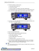
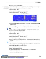
6. Press the YES softkey. The oximeter sounds three beeps to indicate the defaults
have been saved.
Figure 64.
Save Default Prompt in Response to SAVE Selection
Performance Verification
Overview
This section discusses the tests used to verify performance following repairs or
during routine maintenance. All tests can be performed without removing the
OxiMax N-600x pulse oximeter cover. Perform all tests before the battery charge and
battery performance checks, then perform both battery checks as the last operation
before returning the pulse oximeter to the caregiver. If the pulse oximeter fails to
perform as specified in any test, make all repairs necessary to correct the problem
before returning the oximeter to the caregiver.
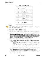
Required Equipment
Table 20.
Equipment and Descriptions
Equipment
Description
Digital multimeter (DMM)
Fluke Model 87 or equivalent
Durasensor™ Adult Finger Clip Sensor
DS-100A sensor
OxiMax™ pulse oximetry sensor
MAX-A sensor
Safety analyzer
Must meet current AAMI ESI:1993 & IEC
60601-1:1988 + A1:1991 + A2:1995 specifications
Pulse oximetry cable
DOC-10 cable
Data interface cable
RS-232 cable (optional)
Stop watch
Manual or electronic
Nellcor model SRC-MAX functional oximetry tester
Provides testing for DigiCal compatible oximeters
9-pin to 15-pin D-connector with all pins shorted together
Provides testing for
Summary of Contents for OXIMAX N-600X Series
Page 8: ...viii 10030881 Rev B 12 2008 Service Manual...
Page 12: ...Safety Information 12 10030881 Rev B 12 2008 Service Manual...
Page 44: ...Theory of Operations 44 10030881 Rev B 12 2008 Service Manual...
Page 96: ...Managing the Data Port 96 10030881 Rev B 12 2008 Service Manual...
Page 188: ...Oximeter Schematics 188 10030881 Rev B 12 2008 Service Manual Main PCB Schematic Sheet 1 of 13...
Page 189: ...Service Manual 10030881 Rev B 12 2008 189 Main PCB Schematic Sheet 2 of 13...
Page 191: ...Service Manual 10030881 Rev B 12 2008 191 Main PCB Schematic Sheet 4 of 13...
Page 192: ...Oximeter Schematics 192 10030881 Rev B 12 2008 Service Manual Main PCB Schematic Sheet 5 of 13...
Page 194: ...Oximeter Schematics 194 10030881 Rev B 12 2008 Service Manual Main PCB Schematic Sheet 7 of 13...
Page 195: ...Service Manual 10030881 Rev B 12 2008 195 Main PCB Schematic Sheet 8 of 13...
Page 197: ...Service Manual 10030881 Rev B 12 2008 197 Main PCB Schematic Sheet 10 of 13...
Page 200: ...Service Manual 10030881 Rev B 12 2008 200 Main PCB Schematic Sheet 13 of 13...
Page 201: ...Service Manual 10030881 Rev B 12 2008 201 Main PCB Assembly Drawing Front View...
Page 204: ...Oximeter Schematics 204 10030881 Rev B 12 2008 Service Manual...
Page 209: ......