Theory of Operations
42
10030881 Rev. B 12-2008
Service Manual
Rate Delay feature distinguishes clinically significant events from minor and brief
pulse rate limit violations that result in nuisance alarms.
To use the Pulse Rate Delay feature, set the traditional alarm management upper and
lower pulse rate alarm limits. Then, set the Pulse Rate Delay. The Pulse Rate Delay
limit controls the time the pulse rate level crosses either limit before an audible alarm
sounds. Refer to
Using the Pulse Rate Delay Alarm Management Feature
managing pulse rate alarms.
OxiMax SPD™ Alert Feature
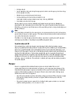
The OxiMax SPD™ Alert (SPD) method of detecting patterns of desaturation in adults
is a function of the software within the OxiMax N-600x pulse oximeter, which detects
repetitive occurrences of desaturation followed by resaturation. These patterns are
indicative of repetitive reductions in airflow through the upper airway and into the
lungs. When SPD is enabled, the default value for SatSeconds is set to100. Set the
upper and lower SpO
2
alarm limits using traditional alarm management methods.
Set the alarm type to visual only or audio and visual. The default setting of one (1) is
the most sensitive to patterns of desaturation. Select from three alarm sensitivity
settings: 1 (most sensitive), 2 (medium sensitivity) or 3 (least sensitive), with 1
resulting in more alarms and 3 resulting in fewer alarms, or turn it to OFF. The alarm
sensitivity value appears directly under the SPD triangle icon. Refer to
, page 77, for detecting patterns of desaturation.
OxiMax™ Pulse Oximetry Sensor Technology
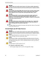
Use OxiMax™ pulse oximetry sensors, which are specifically designed for use with the
oximeter. Identify OxiMax pulse oximetry sensors by the deep blue and/or white
colors of the plugs. All OxiMax pulse oximetry sensors contain a memory chip
carrying information about the sensor which the oximeter needs for correct
operation, including the sensor’s calibration data, model type, troubleshooting
codes, and error detection data.
This unique oximetry architecture enables several new features. When an OxiMax
pulse oximetry sensor is connected to the OxiMax N-600x pulse oximeter, the
oximeter reads the information from the OxiMax pulse oximetry sensor memory
chip, ensures it is error free, and then loads the sensor data prior to monitoring for
new information. As the oximeter reads sensor information, it flashes the sensor
model number on its display. This process may take a few seconds. Once the reading
process is complete, the sensor model number stops flashing and monitoring
begins. The sensor model number disappears after the pulse oximeter starts tracking
the patient’s SpO
2
and pulse rate.
Pulse oximeters containing OxiMax technology, including the OxiMax N-600x pulse
oximeter, use calibration data contained in the OxiMax pulse oximetry sensor in
calculating the patient’s SpO
2
. With sensor calibration, the accuracy of many sensors
is improved, since the calibration coefficients can be tailored to each OxiMax pulse
oximetry sensor. Consult the accuracy card included with the oximeter for specific
Summary of Contents for OXIMAX N-600X Series
Page 8: ...viii 10030881 Rev B 12 2008 Service Manual...
Page 12: ...Safety Information 12 10030881 Rev B 12 2008 Service Manual...
Page 44: ...Theory of Operations 44 10030881 Rev B 12 2008 Service Manual...
Page 96: ...Managing the Data Port 96 10030881 Rev B 12 2008 Service Manual...
Page 188: ...Oximeter Schematics 188 10030881 Rev B 12 2008 Service Manual Main PCB Schematic Sheet 1 of 13...
Page 189: ...Service Manual 10030881 Rev B 12 2008 189 Main PCB Schematic Sheet 2 of 13...
Page 191: ...Service Manual 10030881 Rev B 12 2008 191 Main PCB Schematic Sheet 4 of 13...
Page 192: ...Oximeter Schematics 192 10030881 Rev B 12 2008 Service Manual Main PCB Schematic Sheet 5 of 13...
Page 194: ...Oximeter Schematics 194 10030881 Rev B 12 2008 Service Manual Main PCB Schematic Sheet 7 of 13...
Page 195: ...Service Manual 10030881 Rev B 12 2008 195 Main PCB Schematic Sheet 8 of 13...
Page 197: ...Service Manual 10030881 Rev B 12 2008 197 Main PCB Schematic Sheet 10 of 13...
Page 200: ...Service Manual 10030881 Rev B 12 2008 200 Main PCB Schematic Sheet 13 of 13...
Page 201: ...Service Manual 10030881 Rev B 12 2008 201 Main PCB Assembly Drawing Front View...
Page 204: ...Oximeter Schematics 204 10030881 Rev B 12 2008 Service Manual...
Page 209: ......


