


Data Port Connectivity
Service Manual
10030881 Rev. B 12-2008
81
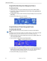
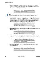
Figure 38 illustrates the pin layouts as viewed from the rear panel. The conductive
shell connects to earth ground when connected to a PC or printer.
Figure 38.
Data Port Pin Layout
Note:
When the oximeter is turned off, the contact at pin 7 is closed and pin 8 is open.
Data Port Communications
Send data from the oximeter to a computer by using a data cable with a Null modem
connector or cross-type cable installed between the oximeter and the computer.
Select the ASCII comm protocol (see
, page 84). Data sent to
the computer is serial, eight (8) data bits, no parity, one (1) stop bit XON/XOFF flow
control and is space-delineated. After making the connection, real-time data flows to
the computer. Every two seconds, the oximeter sends a new line of data. See
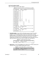
Holding the Ctrl-key on the computer keyboard and pressing “C” twice accesses an
interactive mode. Activating the interactive mode halts the real-time serial output,
while accepting serial input. The oximeter displays five options on the computer
screen while accepting serial input.
These options provide the caregiver or technician the opportunity to request
printouts and to adjust the oximeter date and time.
1.
Dump Instrument Info
—Prints or displays single line of oximeter data, including
the oximeter software version, CRC number, and total operating time. Information
useful to Nellcor’s personnel.
2.
Set Date and Time
—When the oximeter ships from the factory, the date and
time are set to the local factory time zone. If battery removal or disconnection
occurs, the time clock will not reflect the actual date and time. After restoring
battery power, use this feature to change the date and time via the computer. The
format for date and time is DD-MM-YY HH:MM:SS. Move the cursor under the
value to be changed and enter the new value.
Summary of Contents for OXIMAX N-600X Series
Page 8: ...viii 10030881 Rev B 12 2008 Service Manual...
Page 12: ...Safety Information 12 10030881 Rev B 12 2008 Service Manual...
Page 44: ...Theory of Operations 44 10030881 Rev B 12 2008 Service Manual...
Page 96: ...Managing the Data Port 96 10030881 Rev B 12 2008 Service Manual...
Page 188: ...Oximeter Schematics 188 10030881 Rev B 12 2008 Service Manual Main PCB Schematic Sheet 1 of 13...
Page 189: ...Service Manual 10030881 Rev B 12 2008 189 Main PCB Schematic Sheet 2 of 13...
Page 191: ...Service Manual 10030881 Rev B 12 2008 191 Main PCB Schematic Sheet 4 of 13...
Page 192: ...Oximeter Schematics 192 10030881 Rev B 12 2008 Service Manual Main PCB Schematic Sheet 5 of 13...
Page 194: ...Oximeter Schematics 194 10030881 Rev B 12 2008 Service Manual Main PCB Schematic Sheet 7 of 13...
Page 195: ...Service Manual 10030881 Rev B 12 2008 195 Main PCB Schematic Sheet 8 of 13...
Page 197: ...Service Manual 10030881 Rev B 12 2008 197 Main PCB Schematic Sheet 10 of 13...
Page 200: ...Service Manual 10030881 Rev B 12 2008 200 Main PCB Schematic Sheet 13 of 13...
Page 201: ...Service Manual 10030881 Rev B 12 2008 201 Main PCB Assembly Drawing Front View...
Page 204: ...Oximeter Schematics 204 10030881 Rev B 12 2008 Service Manual...
Page 209: ......