4
123456
123456
123456
123456
123456
123456
PART NAMES AND FUNCTIONS
.
Front Terminal Panel
REMOTE 2
R
G
B
H / V
V
REMOTE 1
OPTION 1
S-VIDEO VIDEO
POWER
AC INPUT
ACAT
H/V&V
HIGH
75
W
1
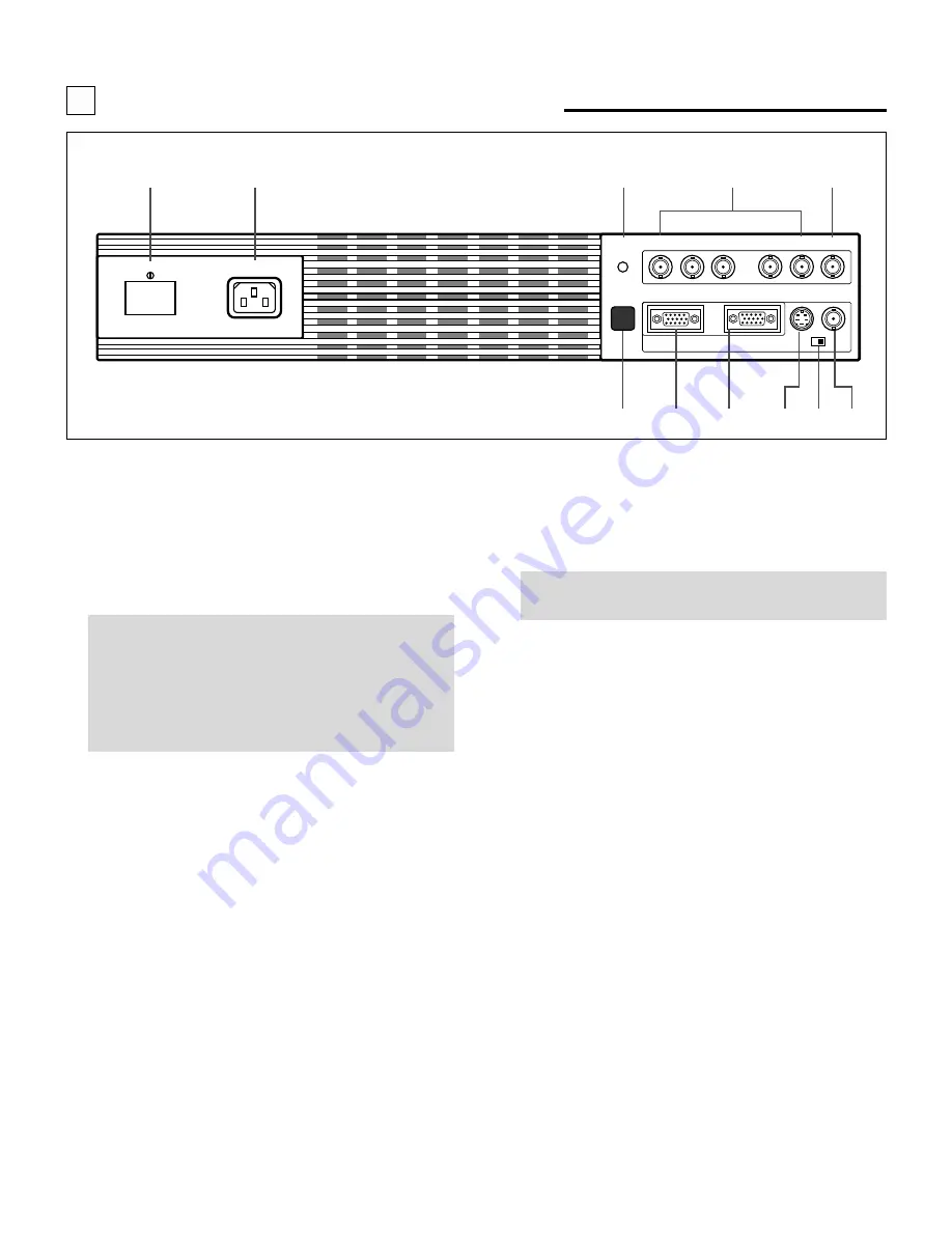
POWER Switch (Main power)
Press to turn the main power on. The STANDBY indica-
tor will light.
In this condition you can start up the projector by pressing
the POWER ON button on the remote control or the
POWER button on the rear panel.
Press again to turn the main power off.
NOTE: When turning off the main power, first return the
projector to the standby condition by pressing the
POWER OFF button on the remote control or the POWER
button on the rear panel and then turn off the main
POWER switch. These procedures are to protect your
projector and the connected equipment.
2
AC INPUT
Connect the supplied power cord here.
3
REMOTE 2 Jack
The supplied full function remote control is connected
here. The wireless control does not work when the remote
cable plug is inserted here.
4
R,G,B, H/V and V Input Terminals
Connect R, G, B, H (Horizontal sync) and V (Vertical
sync) outputs of the external equipment (such as the
Switcher). If using a component with a combined sync
(SYNC) output, connect it to the H/V terminal.
5
Remote Sensor
Receives the infrared signal from the supplied remote
control when used in the wireless mode.
6
REMOTE 1 Terminal
This terminal allows external control of the projector
either from the Switcher or from an external control.
When using the Switcher, connect to the REMOTE 1
terminal on the back of the Switcher.
NOTE: The ISS-6010/ISS-6010G Switcher is compatible
with this projector.
7
OPTION 1 Input Terminal
For future system expansion.
8
S-VIDEO Input Terminal
Connect to the S-video output of the external equipment
such as VCR with an S-video output. This terminal allows
switching between S2 and S1 VIDEO input modes.
9
H/V, V Impedance Switch(HIGH/75
Ω
)
Selects the impedance of the H/V and the V terminals. In
normal operation, set at the “75
Ω
” position.
Slide the switch to the “HIGH” position when inputting a
TTL signal.
0
VIDEO Input Terminal
Connect to the video output of the external equipment
such as a VCR or laser disk player.
A
ACAT Terminal
This is a video output connector for the optional built-in
CCD camera, which is needed to execute the automatic
convergence with the optional ACAT software.
1
2
3
4
A
8 9 0
7
6
5


