background image

2-18 Setting Up Your Server

Connection to Serial Ports

Various types of serial devices can be connected to the RJ-45 serial ports on the front and rear
panels of the server. Some devices require the setting of the jumper pin (J6A2) on the system
board to be changed according to the DCD/DSR signal specification, or they need to be
connected via an optional serial port conversion cable.

A set of two optional serial port conversion cables is provided with the server. The "F" labeled
cable is used to connect devices to the RJ-45 serial ports on the front of the server and the "R"
label cable is used to attached devices to the RJ-45 serial ports on the rear of the server.

IMPORTANT:

Inter-equipment potential difference may cause a server

failure. Be sure to turn off the server and the connection-destination
equipment and disconnect the power cord before
connecting/disconnecting the cable to/from the serial port.

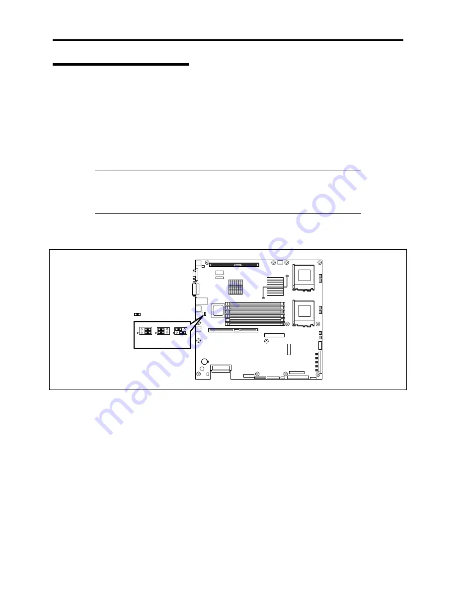
The figure below shows the location of the jumper pin (J6A2). For procedures to dismount the
cover and other internal components see Chapter 7.

Strapped

* Factory-set

J6A2

DCD

DSR

DCD+

DSR*

Summary of Contents for Express5800/120Rd-2

Page 1: ... S e r v i c e G u i d e EXPRESS5800 120Rd 2 ...

Page 2: ...xxx ...

Page 3: ... S e r v i c e G u i d e EXPRESS5800 120Rd 2 ...

Page 4: ...arranted by NEC Computers Inc To allow for design and specification improvements the information in this document is subject to change at any time without notice Reproduction of this document or portions thereof without prior written approval of NEC Computers Inc is prohibited Trademarks AcceleRAID 160 and AcceleRAID 352 are trademarks of Mylex Corporation MS DOS is a registered trademark of Micro...

Page 5: ...lies 1 17 Peripheral Bays 1 17 SAF TE Logic 1 18 System Board Features 1 18 Processor 1 18 Memory 1 18 PCI Riser Slots 1 19 Video 1 19 SCSI Controller 1 19 Network Controller 1 20 Network Teaming Features 1 21 Keyboard and Mouse 1 23 RJ 45 Serial Port 1 23 ACPI 1 23 System Board Management Controller BMC 1 24 Degradation Feature 1 25 Remote Power On Feature Wake On LAN 1 25 AC LINK Feature 1 25 Sy...

Page 6: ...BIOS SETUP 3 1 Starting the SETUP Utility 3 2 Description of On Screen Items and Key Usage 3 3 Configuration Examples 3 4 Menu and Parameter Descriptions 3 9 SCSI BIOS SCSISelect 3 31 Using SCSISelect Utility 3 31 Configuring SCSI Controller on Mother Board 3 31 Configuring SCSI Controller on Optional Board 3 40 Configuring Mother Board Jumpers 3 41 Chapter 4 Installing the Operating System 4 1 Ab...

Page 7: ... Diagnostics 5 8 Relocating Storing the Server 5 10 Chapter 6 Troubleshooting 6 1 System Viewers 6 2 LEDs 6 2 Error Messages 6 3 Error Messages after Power on 6 3 POST Error Messages 6 4 Beep Codes 6 9 Solving Problems 6 10 Problems with the Server 6 10 Problems with EXPRESSBUILDER 6 19 Problems with Express Setup 6 20 Error Message during Disk Array Configuration 6 25 Problems with Master Control...

Page 8: ... a Chassis Handle 7 67 Replacing a Fan 7 68 Replacing the Front Panel Board 7 73 Replacing the SCSI Backplane 7 75 Replacing the Power Supply Cage 7 77 Replacing the System Board 7 78 Chapter 8 Illustrated Parts Breakdown 8 1 Exploded View 8 2 Field Replaceable Units 8 3 Cables List 8 5 Processors 8 6 Memory Expansion 8 7 Hard Disk Drives 8 8 RAID Controllers and Cache 8 9 Backup Tape Drive 8 10 R...

Page 9: ...ing Microsoft Windows NT 4 0 Operating System C 7 Installing LAN Adapter Drivers C 8 Driver Installation for the ATI RAGE XL Display Adapter C 9 Appendix D Product Configuration Record Table D 1 Hardware D 1 Software D 3 Glossary 0 1 ...

Page 10: ......

Page 11: ... cable connections and power on your system Chapter 3 Configuring Your System tells you how to configure the system and provides instructions for running the BIOS Setup Utility and the Adaptec Configuration Utility which is used to configure SCSI devices in your system This chapter also provides information on system board jumper settings Chapter 4 Installing the Operating System describes how to ...

Page 12: ...sed for reference when installing an optional device Appendix C Installing Windows 2000 Windows NT 4 0 describes how to install Microsoft Windows 2000 and Microsoft Windows NT 4 0 without using Express Setup Appendix D Product Configuration Record Table provides a table for documenting your system configuration and future updates you may make to your system Glossary defines the standard acronyms a...

Page 13: ...s ignored Symbols Precautions and notices against hazards are represented with one of the following three symbols This symbol indicates the presence of a hazard if the instruction is ignored An image in the symbol illustrates the hazard type Attention This symbol indicates prohibited actions An image in the symbol illustrates a particular prohibited action Prohibited Action This symbol indicates m...

Page 14: ...r s guide at the time it was developed and released Getting Started Sheet The Getting Started Sheet provides several easy to follow steps to become familiar with your server documentation and to complete your installation successfully System User s Guide The User s Guide provides a quick reference to information about your system Its goal is to familiarize you with your system and the tasks necess...

Page 15: ...doing the procedures in this manual make sure that your system is powered off and unplug the AC power cord from the back of the chassis Failure to disconnect power before opening your system can result in personal injury and equipment damage In the U S A and Canada the power cord must be a UL listed detachable power cord in Canada CSA certified type ST or SJT 16 AWG 3 conductor provided with a mol...

Page 16: ... the external ports Remote Earths To prevent electrical shock connect all local individual office computers and computer support equipment to the same electrical circuit of the building wiring If you are unsure check the building wiring to avoid remote earth conditions Earth Bonding For safe operation only connect the equipment to a building supply that is in accordance with current wiring regulat...

Page 17: ...ystem warm or cool to room temperature before using it Keep the system away from magnetic forces Keep the system dry Do not wash the system with a wet cloth or pour fluid into it Protect the system from being bumped or dropped Check the system for condensation If condensation exists allow it to evaporate before powering on the system Keep the system away from dust sand and dirt ...

Page 18: ...xvi Using This Guide This page is intentionally left blank ...

Page 19: ...rview The System Overview chapter provides the information necessary to use your server and includes a description of your system s major components and functions Read this chapter to familiarize yourself with your server ...

Page 20: ...IA 19 inch rack assembly Your server includes a 3 5 inch diskette drive a CD ROM drive six hot swap SCSI hard disk drive bays and a removable media device bay The hot swap SCSI hard disk drive bays support up to seven 1 0 inch SCSI hard disk drives that can be swapped in or out of the system without powering it down if RAID functionality is configured in the system Alternately your server can be c...

Page 21: ...reen This lamp is on while the system is connected to the network The number 1 on the icon indicates LAN port 1 and the number 2 indicates LAN port 2 5 STATUS lamp green amber on the front panel This lamp indicates the server status The lamp is green during normal operation The lamp turns amber or flashes when the server enters an abnormal state 6 DISK ACCESS lamp green amber This lamp is green du...

Page 22: ...access to the hard disk The lamp turns amber when the hard disk fails The lamp flashes switching back and forth between green and amber during build processing disk array configuration 5 Flex bay A hard disk CD ROM or floppy disk drive can be mounted in this bay A CD ROM or floppy disk drive is mounted in the standard configuration If a hard disk drive is mounted SCSI ID8 is assigned to the bay 6 ...

Page 23: ...er 11 Lamps See the previous figure for a description of these six lamps 12 POWER switch Press this switch to turn the server on off Pressing the switch once turns on the power and the POWER lamp is lit Pressing this switch again turns off the power Once power is applied to the server pressing this switch for 4 seconds or more turns off the power 13 Reset switch Press this switch to reboot the ser...

Page 24: ...can be connected only to serial port 2 Changes to BIOS settings may be required A leased line cannot be connected directly to this connector 6 Mouse keyboard connectors Connect the mouse and keyboard to the connectors through the provided relay cables 7 Rear serial port 2 connector Connect device having a serial interface to this connector BIOS settings may require changes depending on the device ...

Page 25: ...ower failure occurs 14 Power supply unit extension slot power supply slot 2 An optional power supply unit may be installed in this slot The slot when empty is protected with the blank cover 15 AC inlet for the power supply unit provided as standard Connect the power cord to this socket when the power supply unit is mounted in power supply slot 0 16 AC inlet for an additional power supply unit Conn...

Page 26: ... standard in slots 1A and 1B 6 System board 7 Riser card for only low profile boards 8 Cooling fans Each number following the bold faced number indicates the corresponding fan name 8 1 System FAN 3 8 2 System FAN 1 9 Cover open sensor 10 Front LED board 11 CD ROM drive 12 Backup device bay 13 Floppy disk drive 14 Flex bays 15 Disk bays 1 2 3 4 5 6 7 8 1 8 2 9 10 11 12 13 14 15 ...

Page 27: ...nectors 7 1 System FAN 3 7 2 System FAN 1 8 Peripheral interface connector 9 Main power connector 10 Power signal connector 11 SCSI IPMB connector 12 Configuration jumper switch 13 Internal SCSI connector 14 Connector for the access lamp Connect the LED relay cable of an additional SCSI disk array controller 15 Speaker 16 Lithium battery 17 Connector for the PCI riser card For full height boards 6...

Page 28: ...server is operating normally If the STATUS lamps are off or turn amber and flash it indicates that the server is in an abnormal state The table below provides more details on the system STATUS lamps NOTES If ESMPRO or the offline maintenance utility is installed you can confirm the cause of a failure by referring to the error log If shutdown processing can be performed through the operating system...

Page 29: ...f and then turn it on If the POST screen displays an error message note the message and contact your sales representative Off A memory dump request is made Wait until the memory dump is completed A temperature alarm was detected Clean the internal fans Check that no cables are obstructing the internal airflow If the error persists contact your field service representative A voltage alarm was detec...

Page 30: ... that rebuild reconstruction processing is being performed for a hard disk connected to the internal disk array controller IMPORTANT If a hard disk in the server is connected to a disk array controller the access lamp signal cable provided with the server must be connected from the disk array controller to the system board ACT Lamp The ACT lamp is green while the server is connected to the LAN The...

Page 31: ... as soon as possible and perform reconstruction rebuild processing The failing disk can be replaced in hot swap mode Flashing switching back and forth between green and amber The lamp indicates that reconstruction rebuild processing is being performed for the hard disk This flashing does not indicate a failure When a failing hard disk is replaced in disk array configuration the system automaticall...

Page 32: ...the status of the standard network port of the server While power is supplied to the server and HUB and the connection is correct the lamp is on green The lamp turns green and flashes while the network port is transmitting receiving data ACT If the lamp does not go on when the port is connected to the LAN port check the network cable If the lamp does not go on and the network cable has checked out...

Page 33: ...turned on or if it turns amber the power supply unit is probably faulty In this case contact your sales representative to replace the power supply unit NOTE If one power supply unit fails while an optional power supply is installed the system can continue operation with the other power supply unit Redundant function The failing power supply unit can be replaced in hot swap mode with the power on w...

Page 34: ...e format support POWER switch mask Software power off Remote power on feature AC LINK feature Baseboard Management Controller BMC Consoleless feature Self diagnosis Memory monitoring feature 1 bit error correction 2 bit error detection CPU memory degradation feature logical isolation of a failed device Bus parity error detection Temperature detection Error notification Internal fan monitoring feat...

Page 35: ...ration your server includes either six or seven hot swap SCSI hard disk drive bays for mounting hard disk drives installed in easily removable drive carriers NOTE The hot swap SCSI hard disk drive bays contain a hot swap back plane that require an 80 pin single connector attachment SCA connector on the drives that you install The flex bay can be used with either the standard CD ROM FDD module or a...

Page 36: ...o unnoticed until data loss SYSTEM BOARD FEATURES The following subsections describe the system board major components Processor The system board accommodates one or two Intel Pentium III processors with 512k cache in the FC PGA2 package This processor uses the 13 micron technology and offers advanced performance The processor external interface operates at a maximum of 133 MHz Memory The system b...

Page 37: ...3D CRT and LCD monitors up to 100 Hz vertical refresh rate The system board supports disabling of the onboard video through the BIOS setup menu or when a plug in video card is installed in any of the PCI slots SCSI Controller The system board includes an embedded Adaptec AIC 7899W controller providing dual Ultra160 Low Voltage Differential LVD SCSI channels The SCSI bus is terminated on the system...

Page 38: ...Y IEEE 820 3u auto negotiation support Chained memory structure similar to the 82559 82558 82557 and 82596 Full duplex support at both 10 Mbps and 100 Mbps operation Low power 3 3 V device IP checksum off loading On the system board NIC 1 can be used as both a network interface and server management interface NIC Connector and Status LEDs The 82550 controller drives LEDs on the network interface c...

Page 39: ...led switch To set up an option read the instructions in the Windows NT 4 0 or NetWare readme files General Configuration Notes 1 Windows NT versions prior to 4 0 do not support Adapter Teaming options 2 Adapter Teaming options require NT 4 0 with Service Pack 4 0 or Service Pack 3 0 and the Windows Hot Fix 3 In Windows NT teaming options cannot be implemented on adapters that have been configured ...

Page 40: ... select the best adapter based on adapter model and speed Mixed Adapter Teaming AFT supports up to eight server adapters per team in any mix Adaptive Load Balancing Adaptive Load Balancing ALB is a simple and efficient way to increase your server s transmit throughput With ALB you group server adapters in teams to provide an increased transmit rate up to 8 Gbps using a maximum of eight adapters Th...

Page 41: ...ither standard the J6A2 jumper block located directly behind the rear RJ45 serial port must be jumpered appropriately according to which standard is desired See Chapter 2 for detail explanation ACPI The system board supports the Advanced Configuration and Power Interface ACPI as defined by the ACPI 1 0 and PC97 specifications An ACPI aware operating system can put the system into a state where the...

Page 42: ... the nonvolatile System Event Log SEL The events being monitored include over temperature and over voltage conditions fan failure or chassis intrusion To enable accurate monitoring the BMC maintains the nonvolatile Sensor Data Record SDR from which sensor information can be retrieved The BMC provides an ISA host interface to SDR sensor information so that software running on the server can poll an...

Page 43: ...ket from the management computer to a remote server to turn it on if the server is off powered To enable this feature you must select Enabled for Wake On LAN in the Wake On Event of the System Hardware menu of the BIOS setup utility SETUP See Chapter 3 The remote power on feature is not available in the following cases Press the POWER switch once to start the OS and turn off the server in an appro...

Page 44: ...the BIOS Setup Utility The BIOS Setup Utility provides a number of security features to prevent unauthorized or accidental access to the system Once the security measures are enabled you can access the system only after you enter the correct password s For example Enable the keyboard lockout timer so that the server requires a password to reactivate the keyboard and mouse after a specified time ou...

Page 45: ...f you want to enter BIOS Setup and have access to all of the options May enter either password to boot the server if Password on Boot is enabled in either the BIOS Setup May enter either password to exit secure mode Secure Mode Configure and enable the secure boot mode by using the BIOS Setup When secure mode is in effect You can boot the server and the operating system will run but you must enter...

Page 46: ...secure mode or not use the Setup main menu Floppy Options and specify Floppy Access as read only Set a time out period so that keyboard and mouse input are not accepted Also screen can be blanked and writes to diskette can be inhibited Specify and enable an inactivity time out period of from 1 to 120 minutes If no keyboard or mouse action occurs for the specified period attempted keyboard and mous...

Page 47: ... it is present and displays a message Specify the boot sequence The sequence that you specify in setup will determine the boot order If secure mode is enabled a user password is set then you will be prompted for a password before the server fully boots If secure mode is enabled and the Secure Boot Mode option is also enabled the server will fully boot but will require a password before accepting a...

Page 48: ...ilures The major functions of the EXPRESSBUILDER are To install the OS It installs an operating system To diagnose the system It diagnoses the server To create a support disk It copies utilities in the EXPRESSBUILDER CD ROM into a floppy disk to launch them from the floppy disk To update the Windows System It updates the several resources of Microsoft Windows 2000 or Windows NT To install the util...

Page 49: ...or proactive maintenance and fault analysis of the server Normally this utility is used by the maintenance engineer Refer to Chapter 6 for details SYSTEM DIAGNOSTIC UTILITY The system diagnostic utility contained in the EXPRESSBUILDER is useful to prevent the hardware failures Refer to the EXPRESSBUILDER User s Guide located on your EXPRESSBUILDER CDROM for details NEC MANAGEMENT WORKSTATION APPLI...

Page 50: ...must unlock the door with the provided security key Installing or Removing the Front Bezel When turning the power of the server on off accessing to the floppy disk drive CD ROM drive or a removable media device or installing or removing a hard disk from the 3 5 inch device bay first remove the front bezel IMPORTANT The front bezel can be opened only when you unlock it by using the security key 1 I...

Page 51: ... left to remove the tab from the frame and then remove the front bezel from the server 4 To install the front bezel latch the tab at the left side of the front bezel on the server frame After the installation lock the front bezel for security Tab Frame ...

Page 52: ...l device such as a UPS Uninterruptible Power Supply make sure that the power control device is powered up When power is applied to the server an initial diagnosis of the hardware starts The POWER switch does not work while in diagnosis Wait for about 10 seconds after power up then press the POWER switch to turn the server off Do not turn off the server until characters following the NEC logo appea...

Page 53: ... the server the logo appears on the display unit while POST is in progress To display the POST check results press Esc NOTE You can set the POST check results to appear on the display unit without pressing Esc To do so select Enabled for Boot time Diagnostic Screen under the Advanced menu of the BIOS Setup Utility It is not necessary to check the POST check results Check messages that POST display...

Page 54: ... screen The memory check may takes a few minutes to complete depending on the memory size of the server Also it may take approximately one minute for the screen display to appear after rebooting the server 2 Some messages appear upon completion of the memory check These messages appear to indicate that the system has detected the CPU keyboard and mouse 3 After a few seconds POST displays the follo...

Page 55: ...riser card in ascending order of the slot numbers and displays the message indicating activation of the SCSI BIOS SETUP utility If the system drive is to be connected to a SCSI controller board e g a disk array controller connect it to the PCI slot 1C for a low profile board 5 POST displays SCSI ID numbers used by the connected SCSI devices on the screen 6 If an optional disk array controller is i...

Page 56: ...arm messages are useful information for maintenance Power Off Follow the procedure below to power off the server If the power cord of the server is connected to a UPS refer to the manual that comes with the UPS or the manual for the application that controls the UPS IMPORTANT Always allow POST to complete before turning off the server 1 Shut down the OS 2 Press the POWER switch on the front of the...

Page 57: ...nt panel is pressed It goes off when the switch is pressed again Maintenance from the rear of the rack has to be carried out in a dark narrow space The interface cable of a server or power supply unit in normal state may be disconnected by accident in this situation To prevent this problem you should start maintenance after confirming the target server by using the UID switch UID switch UID lamp U...

Page 58: ...isk into the floppy disk drive the drive clicks and the eject button on the floppy disk is slightly pushed out NOTES When an unformatted floppy disk is inserted into the floppy disk drive a message prompting formatting is displayed If the floppy disk contains system startup files powering on or restarting the server with the floppy disk inserted boots the system from the floppy disk To eject the f...

Page 59: ...op it Keep the floppy disk in a floppy disk case that protects it from magnetism and dust A floppy disk has a write protect switch that prevents the stored data from accidental erasure You can read data from a write protected floppy disk but you cannot save data into the floppy disk or format it It is recommended that you should write protect any floppy disk containing valuable data unless you are...

Page 60: ...tray ejected from the CD ROM drive Insert a CD into the CD ROM drive using the following procedure 1 Confirm that the power of the server is on with the POWER lamp being lit in green before inserting the CD into the CD ROM drive 2 Press the Eject button on the front of the CD ROM drive The tray comes out a little 3 Hold the tray lightly and pull it out toward you until the tray stops 4 Put the CD ...

Page 61: ...a CD into the CR ROM drive reinstall the CD To remove the CD from the CD ROM drive press the Eject button on the CD ROM drive The CD ROM tray opens If the access lamp is lit in orange the CD is being accessed Confirm that the access lamp is not lit before pressing the Eject button As shown in the figure above hold the tray with a hand and take the end of the CD lightly by the fingers of another ha...

Page 62: ...n of approximately 1 2 mm in diameter and 100 mm in length a straightened large paper clip into the emergency hole on the right front of the CD ROM drive and gently push it in until the tray opens IMPORTANT Do not use a toothpick or plastic stick that is easy to break If the above procedure does not open CD ROM drive contact your service representative 3 Hold the tray and pull it out 4 Remove the ...

Page 63: ...h a pencil or ballpoint pen Keep the CD away from cigarette smoke Do not leave the CD in a high temperature environment e g place exposed to direct sunlight or close to a heater When dust or fingerprints are on the CD wipe the CD from its center to edge with a dry soft cloth slowly and gently Use the CD cleaner to clean the CD Do not use record spray cleaner benzene or thinner Store the CD in a CD...

Page 64: ...1 46 System Overview This page is intentionally left blank ...

Page 65: ...Chapter 2 Setting Up Your Server This chapter describes how to select a site unpack and install your rack mount server make cable connections and power your server ...

Page 66: ... on the server Power on the server and start software setups Setups depend on the optional internal devices installed and the peripheral devices connected Installing the operating system Install an operating system on the server See Chapter 4 Installing the utilities Install the utilities in the provided EXPRESSBUILDER CD ROM Refer to the EXPRESSBUILDER User s Guide located on your EXPRESSBUILDER ...

Page 67: ...al injury Do not use the server in any unapproved location Do not connect the ground line to a gas pipe CAUTION Observe the following instructions to install and use the server safely Failure to follow these instructions may cause a fire personal injury or property damage Do not carry or install the server by yourself Two persons are required to safely carry or install this server Do not pull the ...

Page 68: ...gas is generated chemicals are nearby or chemicals may be accidentally sprayed Location where anti static carpeting is not used Location where some objects may be fall onto of into the rack Location near a device generating an intense magnetic field such as a TV radio broadcast communication antenna power transmission wire or electromagnetic crane If unavoidable contact your sales agent to request...

Page 69: ... prior to unpacking If the shipping boxes are damaged note the damage and if possible photograph it for reference After removing the contents of the containers store the cartons and the packing materials If the contents appear damaged when you unpack the boxes file a damage claim with the carrier immediately ...

Page 70: ...not conform to the relevant standards Disconnect the power cord s before installing or removing the server CAUTION Observe the following instructions to use the server safely Failure to follow these instructions may cause a fire personal injury or property damage Do not carry or install the server by yourself Two persons are required to safely carry or install this server Do not pull the server ou...

Page 71: ...n by wearing an antistatic wrist strap attached to chassis ground when handling system components Electronic devices can be easily damaged by static electricity To prevent damage keep them in their protective packaging when they are not installed in your system Checking Components The following components are needed to install the server into the rack Required Tools A Phillips screwdriver is requi...

Page 72: ...ANT The removed rail assemblies are to be installed on the inner rails later To install each rail assembly on the correct inner rail mark each rail as removed Similarly when installing more than one server distinguish between the pairs of inner rails and rail assemblies of the servers by marking the left and right hand rails 2 Hold the rails and slowly slide them toward the rear of the server unti...

Page 73: ...ghten the screw to temporarily secure the rail assembly and bracket 3 When each rail bracket is installed on the rail assembly the catch tab at the top end of the rail bracket should point upwards like the catch tab at the opposite end of the rail assembly See the Figure below Inner rails Rear side of the rack Catch Catch Front side of the rack Rail assembly Rail bracket Screw holes Use the screw ...

Page 74: ...osely tighten them 3 Carefully align the rear holes of the slide rail assembly with the holes in the rear vertical mounting rail 4 Install two screws that secure the rear of the slide rail assembly to the vertical mounting rail 5 Tighten all four screws holding the slide rail assembly to the vertical mounting rails 6 Repeat steps 1 through 5 for the mounting the right slide rail assembly on the ri...

Page 75: ...s to use the server safely Failure to follow these instructions may cause a fire personal injury or property damage See pages 1 3 to 1 8 for details Do not lift the server only by a single person Do not pinch your finger with mechanical components 1 Extend the sliding rails of the right and left rail assemblies out of the system rack until they are locked ...

Page 76: ... the rack slowly push it in while pressing the release levers on the right and left sides of the server When the server is installed for the first time the tight mechanical parts may offer resistance You may feel strong friction when sliding the server into the rack 3 Confirm that the sliding rails work normally by moving the server in and out of the rack several times The sliding rail can be pull...

Page 77: ...ng the Server 1 Push the server into the rack as far as it will go 2 Tighten the right and left thumbscrews on the front panel to secure the server to the rack 3 Install the front bezel This completes installing of the server Set screws ...

Page 78: ...mechanical components Do not pull any device out of the rack if the rack is unstable Do not pull more than one device out of the rack at one time 1 Release the security lock open and remove the front bezel 2 Confirm that the server is powered OFF and disconnect the power cable and all the interface cables connected to the server 3 If a cable arm is installed remove the two screws securing the cabl...

Page 79: ... two persons holding the bottom of each side of the server slowly slide the server out of the rack 6 Press in the right and left release levers and carefully slide the server from the rack 7 Place the server on a flat stable surface Release lever Screws Handles ...

Page 80: ...with your sales agent for availability of such a device or cable Some third party devices may not be used with this server The total length of a cable including the connection cable in SCSI device is limited by SCSI standards Ask your sales representative for details The internal SCSI cable of the server is 0 5 m long The 100BASE TX 10BASE T LAN connector and the serial port 2 connector of this se...

Page 81: ...onnector The console of a management PC can be connected to only serial port 2 BIOS setting required Connect the console to only serial port 2 on either the front or rear panel This connector is capped for preventing incorrect connection in the standard status 3 Use the provided branch cable 4 Connect the power cord to a circuit breaker of 15 A or less USB device 1 USB device 1 FRONT REAR Device w...

Page 82: ...ded with the server The F labeled cable is used to connect devices to the RJ 45 serial ports on the front of the server and the R label cable is used to attached devices to the RJ 45 serial ports on the rear of the server IMPORTANT Inter equipment potential difference may cause a server failure Be sure to turn off the server and the connection destination equipment and disconnect the power cord be...

Page 83: ...ollowing instructions to use the server safely Failure to follow these instructions may cause a fire personal injury or property damage Do not plug the power cord in to an improper power source Do not connect the power cord to an outlet that has an illegal number of connections Insert the power plug into the outlet as far as it will go Use an authorized power cord only 1 Plug the provided power co...

Page 84: ...nnect the power cord to the SWITCH OUT outlet For constant power connect the power cord to a UN SWITCH OUT outlet Also connect the modem that is in continual service to this outlet Example 2 O U TP UT U NSW ITC HO UT O U TP UT SW ITC HO UT AC 100V50 50H Z When the power cord from the server is connected into a UPS change the BIOS setup of the server to link with power supply to the UPS Change the ...

Page 85: ...ices may require changes to the BIOS SETUP 1 Make sure all external devices such as a video display keyboard and mouse optional have been connected Ensure the server power cord is connected 2 Power on the video display and any other external devices 3 Make sure that the floppy disk drive does not contain a floppy disk and the CD ROM drive does not contain a bootable CD 4 Open the front bezel 5 Pre...

Page 86: ...2 22 Setting Up Your Server POWER lamp POWER switch ...

Page 87: ... information During the memory test POST displays the amount of memory it was able to access and test Depending on the amount of installed memory it may take several minutes to complete the memory test NOTE The factory default setting displays the NEC logo screen at startup During startup you can change the NEC logo screen to the POST messages screen by pressing Esc To change the start up screen u...

Page 88: ...etup of your server EXPRESSBUILDER is support software for the Express5800 server It simplifies the process of installing and configuring your server Refer to the EXPRESSBUILDER User s Guide located on your EXPRESSBUILDER CD for details Before installing the operating system adjust the system date and time by using the BIOS setup utility SETUP See Chapter 3 for details INSTALLING UTILITIES To inst...

Page 89: ...mpleting system setup Without the system information backup data you may not be able to recover the information You can save the information using the following procedures 1 Insert the NEC EXPRESSBUILDER CD into the CD ROM drive and reboot the system 2 Select Tools 3 Select Off line Maintenance Utility 4 Select System Information Management 5 Insert a floppy disk into the floppy disk drive 6 Selec...

Page 90: ...2 26 Setting Up Your Server This page is intentionally left blank ...

Page 91: ... won t need to make changes to the BIOS default settings IMPORTANT The SETUP utility is intended for system administrator use only Incorrect settings of BIOS parameters could make your server inoperable The SETUP utility allows you to set a password The server is provided with two levels of passwords Administrator and User With the Administrator password you can view and change all system paramete...

Page 92: ...reviously set a password with the SETUP utility the password entry screen appears Enter the password Enter password Up to three password entry tries will be accepted If you fail to enter the password correctly for three consecutive times the server halts You can no longer proceed Power off and then power on the server NOTE The server is provided with two levels of password Administrator and User W...

Page 93: ...the screen The highlighted item is currently selected Cursor Selects the Main Advanced Security Server Boot or Exit menu and Changes the value parameter of the selected item When a submenu option an option preceded by is selected these keys are disabled Enter Press Enter to select determine parameters Esc Displays the previous screen F1 Press F1 when you need help on SETUP operations The help scre...

Page 94: ... supply of the server with ESMPRO Manager via the network Select Advanced Advanced Chipset Control Wake On Lan Enabled UPS To link the server power supply with the UPS To power on the server after a power failure when power is supplied from the UPS Select Server After Power Failure Power On To keep the server powered off after a power failure when power is supplied from the UPS if the POWER switch...

Page 95: ...POST check results To use remote wake up feature Via Modem Select Advanced Advanced Chipset Control Wake on Ring Enabled Via LAN Select Advanced Advanced Chipset Control Wake on LAN Enabled Via PCI device Select Advanced Advanced Chipset Control Wake on PME Enabled Via RTC alarm Select Advanced Advanced Chipset Control Wake on RTC Alarm Enabled To control from the HW console Select Boot Quiet Boot...

Page 96: ...onfiguration Bank n and check the status indications n 1 3 The on screen DIMM numbers and socket locations on the system board are shown in the figure below To clear the memory DIMM error information Select Advanced Memory Configuration Memory Retest Enabled and reboot the server Processor 2 Processor 1 Bank 3 DIMM 3B Bank 2 DIMM 2B Bank 1 DIMM 1B Bank 3 DIMM 3A Bank 2 DIMM 2A Bank 1 DIMM 1A REAR ...

Page 97: ...Security Set Administrator Password and enter a password Set Administrator password first then User password To enable disable the POWER switch Select Security Power Switch Inhibit Enabled Select Security Power Switch Inhibit Disabled IMPORTANT Masking the POWER switch disables forced shutdown see Chapter 6 as well as power on off using the POWER switch To set the secure mode Select Security Set U...

Page 98: ...talling removing internal devices Select Advanced Reset Configuration Data Yes Saving the Configuration Data To save the BIOS configuration data Select Exit Exit Saving Changes To discard changes to the BIOS configuration data Select Exit Exit Discarding Changes or Discard Changes To resume the factory set BIOS configuration data Select Exit Load Setup Defaults To save the current settings as user...

Page 99: ...select a submenu from the above menus The following describes available functions and parameters as well as the factory set parameters for each menu Main Start the SETUP utility to display the Main menu Menu items preceded by mark have a submenu Select an option with the mark and press Enter to display its submenu Available options in the Main and descriptions are listed below ...

Page 100: ... 6 seconds 9 seconds 12 seconds 15 seconds 21 seconds 30 seconds Causes the BIOS to insert a delay before attempting to detect IDE drives in the system during POST Primary IDE Master Primary IDE Slave Displays information on the device connected to the channel Some items may be modified however use the factory set values Processor Settings Displays information on processor CPU and menu window to s...

Page 101: ... only Processor Retest Disabled Enabled Clears CPU error information and retests all processors on the next boot Processor 1 CPU ID Numeric 06xx Numeric indicates CPU 1 ID Blank indicates that no processor is installed or if installed the processor failed View only Processor 1 L2 Cache Reports L2 Cache Size for Processor 1 View only Processor 2CPU ID Numeric 06xx Numeric indicates CPU 2 ID Blank i...

Page 102: ...ormation stored by POST This parameter will be reset to No when the server restarts Numlock Off On Enable or disable the Numlock function at system start up If Auto is selected the Numlock function will be enabled when a keyboard entry is detected Factory set IMPORTANT The Boot Monitoring feature is not supported in this server If Reset Config Data is set to Yes boot device priority is also cleare...

Page 103: ...add in card connected to the full height riser card PCI Slot nC ROM n slot number Enabled Disabled Used to enable or disable an option ROM that may be present on a PCI add in card connected to the low profile riser card Factory set NOTES When the LAN controller does not provide network booting set the option ROM for the LAN board to Disabled When connecting a hard disk containing the operating sys...

Page 104: ...board LAN controller Embedded NIC ROM Enabled Disabled Enables or disables onboard LAN controller expansion ROM Factory set Onboard SCSI Submenu Option Parameter Description Your Setting Onboard SCSI Enabled Disabled Enables or disables onboard SCSI controller Onboard SCSI ROM Enabled Disabled Enables or disables onboard SCSI controller expansion ROM Factory set Onboard Video Submenu Option Parame...

Page 105: ...isplay the following screen See the table below for setup options on the screen IMPORTANT Avoid conflicts in the interrupt requests or base I O addresses If an assigned value is already used by another resource it appears in yellow Any yellow value must be re assigned Displayed only when the user password is set ...

Page 106: ...rial Port 1 irq 4 3 Used to configure the interrupt for serial port 2 Diskette Write Protect Disabled Enabled Displayed only when the user password is set Used to allow or inhibit writing into floppy disk Diskette Controller Enabled Disabled Enables or disables onboard floppy disk controller BIOS Legacy USB Support Disabled Keyboard Only Auto Keyboard and Mouse Disables or enables support for USB ...

Page 107: ...Note the smaller the test unit the longer the test takes during POST DIMM Bank 1 3 Installed Disabled Not Installed Indicates the current memory status Normal indicates the normal status Error indicates a memory error and None indicates no DIMM installed view only Bank 1 indicates DIMMs in DIMM socket 1A and 1B Bank 2 indicates DIMMs in DIMM Bank 2A and 2B Bank 3 indicates DIMMs in DIMM Bank 3A an...

Page 108: ...Ring Disabled Enabled Enables or disables the remote power on features via serial port modem Wake on LAN Disabled Enabled Enables or disables the remote power on features via network Wake on PME Disabled Enabled Enables or disables the remote power on features by PCI device PCI Power Management Enable wake up event Wake on RTC Alarm Disabled Enabled Enables or disables the remote power on features...

Page 109: ...elow shows when Set Administrator Password is selected Set a password on this pop up screen Enter a password of up to seven alphanumeric characters and symbols from the keyboard IMPORTANT User password setup is not available before Administrator password setup Do not set any password before installing the OS If you forget any password consult with your sales representative Selectable only when the...

Page 110: ...ssword entry at boot up Administrator password setup is required beforehand When the administrator password is specified and this option is disabled the BIOS assumes that a system boot attempt is made by a user Secure Mode Timer 1 minute 2 minutes 5 minutes 10 minutes 20 minutes 60 minutes 120 minutes Set the period from no input from the keyboard or mouse to the point at which the system enters i...

Page 111: ... up Assert NMI on PERR Disabled Enabled Sets support of PCI PERR Assert NMI on SERR Disabled Enabled Sets support of PCI SERR BMC IRQ Disabled IRQ 5 IRQ 11 Sets the BMC IRQ After Power Failure Stays Off Last State Power On Sets the AC LINK feature Determines the mode of operation if a power loss occurs See the table below Temperature Sensor Disabled Enabled Enables or disables temperature sensor m...

Page 112: ...wer status of the server when the power supply to the server restarts Parameter State before powered off Stays Off Last State Power On In service Off On On Out of service DC power Off Off Off On Forced shutdown Off Off On Pressing the POWER switch for at least four seconds shuts down the power to the server ...

Page 113: ...s the serial number of system board View only System Part Number Indicates the system part number View only System Serial Number Indicates the serial number of system View only Chassis Part Number Indicates the part number of chassis View only Chassis Serial Number Indicates the serial number of chassis View only BIOS Revision Indicates BIOS revision number View only BMC Revision Indicates BMC Bas...

Page 114: ... redirect the console to MWA or remote terminals using hyper terminal Disable the Quiet Boot option in BOOT menu Serial Port COM1 3F8 IRQ4 COM2 2F8 IRQ3 Selects an address interrupt for the serial port used for redirection Make sure to use the same address interrupt as specified in Advanced Peripheral Configuration Baud Rate 9600 19 2k 38 4k 115 2k Selects a baud rate for communications with the c...

Page 115: ... Parameter Description Your Setting Clear All Event Logs No Yes Clears the DMI event log after a system reboot Event Logging Enabled Disabled Specifies whether all systems events are logged or not Critical Event Logging Enabled Disabled Specifies whether to detect and log event at system critical errors Critical errors are fatal to system operation These errors include PERR SERR ECC Memory errors ...

Page 116: ...y Hard Drive Removable Devices and ATAPI CDROM Drives first select a desired option and press Enter to display its submenu See the table below for setup options on the screen Option Parameter Description Your Setting Quiet Boot Disabled Enabled If disabled displays normal POST messages If enabled displays NEC Logo instead of POST messages Enabling this option disables console redirection Factory s...

Page 117: ...our Setting 1st Boot Device Removable Devices Attempts to boot from a removable media device 2nd Boot Device ATAPI CD ROM Drive Attempts to boot from an ATAPI CD ROM drive 3rd Boot Device Hard Drive Attempts to boot from a hard drive device 4th Boot Device Intel Boot Agent ver Attempts to boot from a network PXE boot 5thBoot Device Intel Boot Agent ver Attempts to boot from a network PXE boot Hard...

Page 118: ...devices in the system Select one of the detected devices This list includes legacy 1 44 MB floppy drives and 120 MB floppy drives ATAPI CD ROM Drives Submenu Select the CD ROM drive used to boot the system The system searches for the boot device according to the order specified in this submenu and use the software to boot the system if found Move the cursor to select the device by or Item Descript...

Page 119: ...uration data and exit the SETUP utility Select Yes to discard the current configuration data and exit the SETUP utility and restart the server automatically Select No to return to Exit menu Load Setup Defaults Select this option to resume all default values BIOS default values of the SETUP utility Select Yes to resume default values Select No to return to the Exit menu screen If you resumed the de...

Page 120: ...efaults Save Custom Defaults Select this option and press Enter to save the current configuration data as custom defaults When the configuration is saved the Load Custom Defaults menu appears Discard Changes Select this option to discard any changes made to BIOS settings and restore the previous settings Select Yes to discard the current settings ...

Page 121: ... SCSI configuration must be made on a per SCSI controller basis with a utility The server contains one SCSI controller When you added optional SCSI controllers you need to make configuration for each SCSI controller in addition to the standard internal SCSI controller Some additional SCSI controllers may require a different utility to make changes to the configuration Configuring SCSI Controller o...

Page 122: ...ppears 3 Select 01 06 A or 01 06 B in the Bus Device box with the cursor keys and press Enter You have an AIC 7899 Bus Device Channel SCSI host adapter in your system Move 01 06 A the cursor to the bus device channel of 01 06 B the one to be configured and press Enter F5 Toggle color monochrome The system board is provided with two SCSI controller channels Channel B 01 06 B indicates the Ultra 160...

Page 123: ...iguration Options Press Enter F6 Reset to Host Adapter Defaults 5 Select a parameter for each menu item See the section Parameters described later to set an appropriate parameter for each menu item 6 After completing the parameter settings press Esc repeatedly until the following save message appears Save Changes Made 7 If the configuration data is correct select Yes and press Enter 8 Press Esc re...

Page 124: ...ptional Board described later SCSI Bus Interface Definitions To set three menu items under SCSI Bus Interface Definitions select a menu item with the cursor keys or and press Enter to fix the item Use the cursor keys or for parameter selection The following table lists menu items available parameters and descriptions Menu item Parameter Description Host Adapter SCSI ID 0 7 15 Select 7 SCSI Parity ...

Page 125: ...bmenu Boot Device Configuration Select SCSI peripheral from which to boot To view peripheral by ID select SCSI Disk Utilities from previous menu Boot Channel A First Boot SCSI ID 0 Options Listed Below Have NO EFFECT if MULTI LUN Support Is Disabled Boot LUN Number 0 The following table lists submenu items available parameters and descriptions Submenu item Parameter Description Boot Channel A Firs...

Page 126: ...Yes Yes Yes Yes Yes SCSI Device ID 8 9 10 11 12 13 14 15 Sync Transfer Rate MB Sec 160 160 160 160 160 160 160 160 Initiate Wide Negotiation Yes Yes Yes Yes Yes Yes Yes Yes Enable Disconnection Yes Yes Yes Yes Yes Yes Yes Yes Send Start Unit Command Yes Yes Yes Yes Yes Yes Yes Yes Options Listed Below Have NO EFFECT if the BIOS is Disabled Enable Write Back Cache N C N C N C N C N C N C N C N C BI...

Page 127: ...ted devices appears Select SCSI Disk and press Enter SCSI ID 0 No device SCSI ID 1 No device SCSI ID 2 No device SCSI ID 3 No device SCSI ID 4 No device SCSI ID 5 No device SCSI ID 6 No device SCSI ID 7 AIC 7899 SCSI ID 8 No device SCSI ID 9 No device SCSI ID 10 No device SCSI ID 11 No device SCSI ID 12 No device SCSI ID 13 No device SCSI ID 14 No device SCSI ID 15 No device Find out the SCSI ID f...

Page 128: ...nable Write Back Cache Yes No N C Select N C BIOS Multiple LUN Support Yes No Select No Include in BIOS Scan Yes No Select Yes Factory set Advanced Configuration Options Move the cursor onto Advanced Configuration Options and press Enter to display the following submenu Advanced Configuration Options Reset SCSI Bus at IC Initialization Enabled Display Ctrl A Message During BIOS Initialization Enab...

Page 129: ...an optional SCSI controller If the optional SCSI controller has no hard disks connected however select Enabled BIOS the SCSI controller may be disabled to reserve an area in the expansion ROM space if the controller has no hard disks connected Domain Validation Enabled Disabled NOT Scan Disabled scan bus Enable or disable SCSI BIOS Select Enabled Support Removable Disks under BIOS as Fixed Disks B...

Page 130: ...controller boards installed the server first displays the start up message of the SCSISelect utility for the SCSI controller on the system board It then displays the utility start up message for additional SCSI controllers one by one The start up message appears in order of the PCI board slot numbers of the riser card for low profile type and the riser card for full height type The message display...

Page 131: ...is setting is necessary for operating the server correctly Select Advanced Peripheral Configuration Legacy USB Support Disabled Select Boot Boot Device Priority ATAPI CD ROM Drive 1st Boot Device Select Boot Boot Device Priority Removable Drive 2nd Boot Device Select Boot Hard Disk and set the boot order To clear passwords or the CMOS data use the jumper switch on the system board of the server Th...

Page 132: ... before closing the server Do not install the server in a rack with leaving covers removed Do not pinch your finger within the mechanical components of the server High temperature can result if the server is operated with the covers removed Do not pull a device out of the rack if the rack is unstable Do not pull more than one device out of the rack at one time 1 Loosen the thumbscrews and pull the...

Page 133: ... from the Exit menu and then Yes 7 Wait until the message Turn off power and reinstall the jumper in Normal mode position appears 8 Turn off the system power switch 9 Change the jumper switch setting back to the original position turn on the power and then define the setting by using the BIOS SETUP utility ...

Page 134: ...3 44 Configuring Your System This page is intentionally left blank ...

Page 135: ...ems on your server Microsoft Windows 2000 Microsoft Windows NT 4 0 Novell NetWare Version 5 0 SCO Unix 5 0 To install operating systems not described in this section contact your service representative IMPORTANT Before installing the operating system adjust the system date and time by using the BIOS SETUP utility SETUP See Chapter 3 for detail ...

Page 136: ...is intended for the initial setup of the server system Therefore it clears any prior content of the hard disk For Microsoft Windows 2000 and Windows NT 4 0 Express Setup automatically configures your server and installs the operating system After some initial setup you need to remove the EXPRESSBUILDER CD and insert the Windows CD input a product ID number and acknowledge the license agreement For...

Page 137: ...rt Normal start creates the configuration diskette during Express Setup NOTES To perform Express Setup BIOS Setup must prioritize the CD ROM drive as the first boot up device before the diskette drive and hard drive You can create the configuration diskette in advance using Express Setup for Windows included on EXPRESSBUILDER By creating the configuration diskette in advance fewer parameters need ...

Page 138: ...server supports the following Windows 2000 versions Microsoft Windows 2000 Server version hereinafter referred to as Windows 2000 Microsoft Windows 2000 Advanced Server version hereinafter referred to as Windows 2000 To install Windows NT 4 0 see the next subsection in this chapter To install other operating systems contact your service representative BIOS Specification Before installing Windows 2...

Page 139: ...de when installing Windows 2000 on this server system Do not use the installation guide for installing Windows 2000 that may be packaged with software not supplied with this system Installing Windows 2000 on a Mirrored Volume If you want to install Windows 2000 on a volume that has been mirrored using Disk Management you must invalidate the mirror before re installing the system on a basic disk an...

Page 140: ...e to collect accurate debug information memory dump If you want to install Microsoft Windows 2000 Advanced Server on a system with more than 4GB of memory installed we recommend you increase the default paging file size by 2060MB The dump file size for a system with more than 2GB memory installed is 2048MB 12MB For example if the installed memory size is 512MB the minimum required partition size w...

Page 141: ...n upgraded to a Dynamic Disk using Express Setup If you want to preserve the current partition see Appendix D to re install the system manually Disk Configuration Concerning the area displayed as MAINTE_P Disk Management under Computer Management may display a MAINTE_P partition This area is a maintenance partition which contains configuration information and utilities Do not delete this partition...

Page 142: ...er File No Retrieve again Existing File Select OS New File Terminate Check Setup Parameter File If you need to reset the specification Correct Select whether or not to confirm or modify existing values Confirm the specification and input the value Re select OK Incorrect No Yes Insert Windows 2000 CD After restarting the computer the installation completed Express Setup Log on Automatically Process...

Page 143: ...e Appendix D 1 Power up peripheral devices and then power up the server 2 Insert the EXPRESSBUILDER CD into the CD ROM drive 3 Press the RESET switch or press Ctrl Alt and Delete to boot the EXPRESSBUILDER CD You may also power down then power up to reboot the server The system boots from the CD and EXPRESSBUILDER starts 4 The Language Selection Menu is displayed Select the language and keyboard t...

Page 144: ...p 8 If Skip Go to step 9 Using Blank disk 3 Click the box under Setup File Name A or press A The input box appears 4 Input the file name Operating System to Install appears The OS supported by the computer is displayed in the list 5 Select Windows 2000 from the list box 8 Confirm the contents specified during OS installation Under Language Information specify the language version of the operating ...

Page 145: ...ea If you specify a partition size larger than 2000MB you must specify convert to NTFS If Use Existing Partition at System Partition is selected but the partition selected to install Windows 2000 is the only partition except for maintenance Express Setup will reserve the maximum area of the hard disk to install Windows 2000 You can not go to the next screen if an incorrect value is specified If a ...

Page 146: ...e contents carefully and click I agree or press F8 if you do agree If you do not agree click I disagree or press F3 IMPORTANT If you do not agree to this agreement the setup terminates and Windows 2000 will not be installed If NetWare Gateway and Client Service is to be installed a window to specify the details of NetWare Gateway and Client Service will be displayed at first login 11 If you select...

Page 147: ...log box appears 3 Click Configure The property dialog box for network adapter appears 4 Click Advanced and specify the same Link Speed Duplex value as specified for HUB 5 Click OK on the property dialog box for network adapter 6 Click OK on the Local Area Connection Properties dialog box Also add or delete protocols and services as required Perform these actions from the property dialog box of the...

Page 148: ...under Intel Advanced Network Services The Intel R PROSet II Setup dialog starts 4 In the Welcome window click Next If the dialog message Digital Signature could not been found appears select Yes 5 Click Finish Intel R PROSet II Setup has completed 6 Restart the system Graphic Accelerator Driver Update the installed standard graphic accelerator driver If you want to utilize an optional Graphic Acce...

Page 149: ... and restarting the system All the adapters specified as an Adapter Team must be on the same LAN If they are connected to separate LANs they cannot perform AFT or ALB If you want to utilize AFT ALB feature follow the procedure below to setup 1 Double click Intel R PROSet II on the Control Panel dialog box The Intel R PROSet II dialog box appears 2 Select Intel 8255x based PCI Ethernet Adapter 10 1...

Page 150: ...e stating that the system is short of virtual memory may appear but complete the process If you restart the system the memory dump may not be stored correctly Follow the procedure below to specify 1 Point to Settings in Start menu and click Control Panel The Control Panel dialog box appears 2 Double click System The System Properties dialog box appears 3 Click Advanced 4 Click Startup and Recovery...

Page 151: ...ox 8 Modify Initial Size in the Paging File Size for Selected Drive box to a value larger than Recommended Size and click Specify IMPORTANT The above paging file size is necessary for collecting debug information memory dump If you set the initial value of paging file size smaller than the recommended value you may not be able to collect complete debug information memory dump For more information ...

Page 152: ... dialog box appears 3 Specify the location to store the diagnostic information in the Log File Path box The diagnostic information will be stored with the file name DRWTSN32 LOG NOTE You can not specify a network path The file must be on the local computer 4 Specify the location of crash dump file in the Crash Dump box NOTE Crash Dump File is a binary file that can be read with Windows Debugger 5 ...

Page 153: ...s Wizard dialog box appears 4 Check the Management and Monitoring Tools check box of the component ON and click Next 5 If the setup asks for a disk insert Windows 2000 CD into CD ROM drive and click OK 6 Click Complete in the Windows Component Wizard dialog box 7 Click Close in the Add Remove Application dialog box 8 Close the Control Panel dialog box To start Network Monitor point to Program Admi...

Page 154: ...lect 120Rd 2 and click Windows 2000 NEC Update Module and setup will start After that follow the prompts to continue the setup process and apply the Service Pack Making Backup Copies of System Information The system information includes the current BIOS settings and other information specific to your server You should save this information after completing the system setup This backup data will al...

Page 155: ...section explains precautions and information you should be aware of before beginning installation in order to install Windows NT 4 0 correctly Supported OS on this model The server supports the following Windows NT 4 0 versions Microsoft Windows NT Server 4 0 Described as Windows NT 4 0 later on Microsoft Windows NT Server 4 0 Enterprise Edition Described as Windows NT 4 0 EE later on To install o...

Page 156: ...e installation guide for installing Windows NT 4 0 that may be packaged with other software not supplied with the system Service Pack Express Setup can apply Service Pack 5 or later on the system If you want to apply Service Pack older than Version 5 select Do not Apply in Apply Service Pack item when creating the Setup File to setup the system and perform the System Update described later After c...

Page 157: ...up Domain Controller of Primary Domain Controller that has exceeded the router do not use Express Setup and perform manual setup Specifying Partition Size The minimally required size for the partition to install the system can be calculated from the following expression 200MB Paging File Size Dump File Size 200MB The size necessary for installing the system Paging File Size Recommended Mounted Mem...

Page 158: ...ct whether or not to confirm modify the existing values Confirm input the specification Re select OK abnormal No Yes Install Graphic Accelerator Driver Automatic Installation Log on Automatically Process that continues automatically Process requiring input or selection After the reboot the installation is completed 3 Insert Update Media 4 Insert Windows NT CD Agree to Software License Agreement Co...

Page 159: ...hen creating the Setup File to setup the system and perform System Update described later 1 Turn the power of peripheral devices on and then turn on the server 2 Insert EXPRESSBUILDER CD into the CD ROM drive of the server 3 Press the RESET switch or press Ctrl Alt and Delete to reboot the EXPRESSBUILDER You may also turn off and then on again to reboot the server The system will boot from the CD ...

Page 160: ... Skip Go to step 9 Using Blank disk 1 Click the box under Setup File Name A or press A The input box appears 2 Input the file name Operating System to Install appears The OS supported by the computer is displayed in the list 3 Select NT 4 0 from the list box 8 Confirm the contents specified during OS installation Under Language Information specify the language version of the operating system to be...

Page 161: ...screen if an incorrect value is specified If a specified value is inconsistent with values previously specified it may be necessary to go back to modify them If a partition larger than 4GB is specified you must apply Service Pack 5 or later If so you can not uninstall Service Pack 5 after starting Windows NT NOTES If you click Cancel in Basic Information screen the Express Setup will go back to al...

Page 162: ...ll not be installed 11 When prompted remove configuration diskette from the floppy disk drive and Windows NT CD from the CD ROM drive 12 If you have specified to apply Service Pack 5 or later insert the specified version of Service Pack into CD ROM drive when prompted Windows NT 4 0 is installed automatically and the local administrator is automatically logged on to the system NOTE If Backup Domai...

Page 163: ...operties The Intel R PROSet II dialog box for network adapter appears 4 Click Advanced and specify the same Link Speed Duplex value as specified for HUB 5 Click OK on the Intel R PROSet II dialog box for network adapter 6 Click OK on the Network dialog box Also add or delete any protocols and services as required You can perform these actions from the Network dialog box Click Protocol to display t...

Page 164: ... Control Panel dialog box The Intel R PROSet II dialog box appears 2 Select Intel 8255x based PCI Ethernet Adapter 10 100 in the list and right click Pull down menu appears 3 Select Add to Team and then click Create New Team If Service Pack 5 or later is not applied to the system a window to notify you of that issue will be displayed at this point In this case click OK and go back to Intel R PROSe...

Page 165: ...he process If you re start the system in this case memory the dump may not be stored correctly Follow the procedure below to specify 1 Point to Settings in the Start pop up menu and click Control Panel The Control Panel dialog box appears 2 Double click System The System Properties dialog box appears 3 Click the Startup Shutdown 4 Check Write an event to the system log 5 Check Write debugging info...

Page 166: ...ion If Initial Size of the paging file is specified to the value smaller than Recommended value complete debug information memory dump may not be collected For more information on Recommended value see Specifying Partition Size described earlier In anticipation of problems occurring it is recommended that a dump file always be prepared in advance In case the memory is increased change the paging f...

Page 167: ...ialog box appears 3 Specify the location to store the diagnostic information in the Log File Path box The diagnostic information will be stored with the file name DRWTSN32 LOG IMPORTANT You cannot specify a network path The file must be on local computer 4 Specify the location of crash dump file in Crash Dump box NOTE Crash Dump File is a binary file that can be read with Windows Debugger 5 Check ...

Page 168: ...ted correctly but a message to inform you of that does not appear On Windows NT system repair can be performed by reading the repair information existing on the hard disk so it is not necessary to create a repair floppy diskette IMPORTANT Update System Recovery Information is intended to enable you to start the system when some problem has occurred on the system and the system will not start Updat...

Page 169: ...lation Installing Network Monitor after OS Installation 1 Point to Settings from the Start pop up menu and click Control Panel The Control Panel dialog box appears 2 Double click Network The Network dialog box appears 3 Click Service and click Add The Select Network Service dialog box appears 4 Select Network Monitor Tool and Agent from the Network Service list and click OK The Windows NT Setup di...

Page 170: ...rocedure below to update the system IMPORTANT Be sure to use the Repair Disk Utility to update repair information when the system is updated or install a service pack No Service Pack is included on EXPRESSBUILDER 1 Log on to the system with the account that has administrative authority e g Administrator 2 Insert EXPRESSBUILDER CD into the CD ROM drive of the server 3 The EXPRESSBUILDER screen appe...

Page 171: ...d save this information after completing the system setup This backup data allows you to recover the information You can save the information by the following process 1 Insert the EXPRESSBUILDER CD into the CD ROM drive and reboot the system 2 Select Tools 3 Select Off line Maintenance Utility 4 Select System Information Management 5 Insert a floppy disk in the floppy disk drive 6 Select Save ...

Page 172: ...listed in the table below are located on the EXPRESSBUILDER CD To create the required diskettes perform Custom Setup on the EXPRESSBUILDER CD CAUTION When creating the required diskettes from the EXPRESSBUILDER CD make sure you use the drivers required for the devices on your specific system Supported Device Required Diskette AIC7899 Onboard Controller NetWare OEM Disk for 120Rd 2 NEC SecuRAID 112...

Page 173: ...on Guide and the Disk Array Controller Installation Guide and User s Manual for additional information on this option card If you need to change the RAID level from the factory setting you must change the setting before installing the operating system Configuration Checklist Certain configuration information must be available before loading the Novell NetWare v5 0 Network Operating System The foll...

Page 174: ...y Code and corresponding Code Page Choose the Country Code and corresponding Code Page from the following selections Circle one Country Code and one of the corresponding Code Pages Country Code 1 United States 001 2 French Canada 002 3 Latin America 003 4 Netherlands 031 5 Belgium 032 6 France 033 7 Spain 034 Code Page 1 United States English 437 2 Multilingual 850 1 United States English 437 2 Fr...

Page 175: ...l 351 H Finland 358 1 United States English 437 2 Multilingual 850 1 United States English 437 2 Multilingual 850 1 United States English 437 2 Multilingual 850 1 Multilingual 850 2 Nordic 865 1 United States English 437 2 Multilingual 850 1 United States English 437 2 Nordic 865 1 United States English 437 2 Multilingual 850 1 United States English 437 1 Multilingual 850 2 Portuguese 860 1 United...

Page 176: ...None 5 LAN Adapter Choose which type of LAN adapter is installed in the LAN adapter slot Circle one selection Intel PRO 100 No adapter to configure 6 IPX Network Number Record the IPX Network Number associated with the LAN adapter in slot one For more information about IPX Network Numbers see Network Numbering in the Novell Concepts manual IPX Number _________________________ 7 Repeat steps 5 and ...

Page 177: ...initial file copy then manually create a subdirectory C NWUPDATE copy the new drivers into that directory and restart INSTALL BAT from the NetWare 5 installation CDROM maintaining the existing partitions 1 Power on your server 2 Insert the NetWare 5 0 CD into your CD ROM drive 3 Select a language for your locale and press ENTER 4 Highlight Accept License Agreement from the menu and press ENTER 5 H...

Page 178: ...R Note Repeat steps 25 through 29 for additional Network Boards 28 Press ESC and return to Device Driver Summary 29 Press ESC 30 Highlight Continue Press ENTER 31 Highlight Continue to create a NetWare partition and volume SYS Press ENTER 32 At the Server Properties box type in your server name and click Next 33 At the Protocols box click the Network Board you want to configure 34 Once you made yo...

Page 179: ... and Services desired and click Next to continue 41 Click Finish at the summary screen 42 Remove any diskettes and or CDs and click Yes to restart your server 43 Install the appropriate support pack Restarting the Server You should now restart the server to initialize your changes You can do this by typing the following commands from the Server_name prompt restart server Backing Up the Server You ...

Page 180: ...h the system Depending upon the hardware complement in your system you may require some or all of the diskettes listed in the table below They should be generated before attempting to install the operating system Also listed in the table below are the required diskette labels CAUTION When creating the required diskettes from the EXPRESSBUILDER CD make sure you use the drivers required for the devi...

Page 181: ...ion Refer to the Configuring Your System chapter of your User s Guide for more information on how to run these utilities Configuration Checklist Configuration Checklist Step Information 1 File Server Name Record the file server name for this system File server name _________________________ 2 IP Address Assign an IP address for each LAN card that is to be installed into the system Seven maximum IP...

Page 182: ...optional adapters refer to the installation guide that came with the adapter the SCO documentation and the System User s Guide shipped with your system for installation and configuration information The following optional adapter may be added to your system Disk Array Controller Refer to your system s User s Guide and to the RAID Installation Guide and the Disk Array Controller Installation Guide ...

Page 183: ...Handbook Installation Guide includes an installation checklist to assist you in installing or upgrading to SCO UNIX OpenServer 5 0X Once the installation is complete including all additional options such as Symmetrical Multiprocessing if required the SCO Maintenance Supplement 505A should be added Installation of SCO Maint 505A involves using the software manager and a set of four diskettes genera...

Page 184: ...m displays the message Keyboard Press ENTER 8 The system displays the message Enter License Number and License Code Press ENTER 9 The system displays the message Additional License Software Continue 10 The system displays the message Suitable for Automatic Upgrade Enter appropriate Upgrade or Fresh Press Enter 11 Select OK 12 The system displays the message Configure the Basic System Enter appropr...

Page 185: ...stem has completed its installation you will see the following message Installation and initial configuration of SCO OpenServer Rel 5 0X Enterprise System is complete Press ENTER to continue Press ENTER to continue The system displays Safe to Power Off or Press any Key to Reboot 20 If a SCSI tape drive is attached to channel B of the 7899 perform the following steps This will generate a new idscsi...

Page 186: ...Note During the installation of SCO or any time thereafter when booting SCO a warning message may appear as follows WARNING Cannot connect to APM error 0x0036 System loaded press Return to start To prevent the WARNING message from appearing boot the system to single user Mode Edit the etc default boot file Add apm check no to the end of the line indicated by the DEFBOOTSTR entry It is recommended ...

Page 187: ...efore installing SCO UNIX ensure that system drive 0 boot drive has been configured for write through cache If write back cache has been configured the SCO UNIX root file system may be corrupted at the completion of the installation After the installation is completed the system drive can be toggled to write back cache 1 Insert the SCO OpenServer Version 5 0X CD into the CD ROM drive and boot your...

Page 188: ...t 7 The system displays the message Identifying the installation media device Make sure the IDE indicates CD ROM secondary and master Press ENTER 8 The system displays the message Keyboard Press ENTER 9 The system displays the message Enter License Number and License Code Press ENTER 10 The system displays the message Additional License Software Continue 11 The system displays the message Suitable...

Page 189: ...ed Configuring the kernel driver installation Press ENTER to continue Press ENTER to continue 20 When the system has completed its installation you will see the following message Installation and initial configuration of SCO OpenServer Rel 5 0X Enterprise System is complete Press ENTER to continue Press ENTER to continue The system displays Safe to Power Off or Press any Key to Reboot 21 If a SCSI...

Page 190: ...t this time After all additional software is installed it is recommended that Maintenance Supplement 505A be installed on your system Note Do not change the system drive 0 boot drive cache policy to write back until after the installation completes Installation of Tape Drives After the installation of SCO 5 0X UNIX is complete ensure the tape device is configured to the proper controller If reconf...

Page 191: ...the media device usually the floppy diskette drive and press ENTER click on Continue 6 A dialog box displays the driver s read from the media Select the appropriate driver and press ENTER click on Full 7 A dialog box appears Please use netconfig to configure network software press return to continue Press ENTER 8 A message dialog box displays indicating Installation complete Press ENTER or select ...

Page 192: ...ENTER 14 Press ENTER to continue 15 Reboot your system Configuring Additional Hard Disks Configuring additional hard disk drives requires that they be hardware configured and low level formatted most disks are shipped already low level formatted For SCO UNIX Open System and OpenServer Rel 5 X Software to recognize more than one hard disk drive you must execute a series of commands For a detailed d...

Page 193: ...ware configuration or BIOS configuration select System Information Management and then Save of the Off line Maintenance Utility to make a backup copy of the system information Also make a backup copy of the disk array configuration data if your system includes a disk array controller When your hard disks have been auto rebuilt due to a failure it is recommended you make a backup copy of the config...

Page 194: ...he server Do not look into the CD ROM drive when it is powered up Do not remove the lithium battery Disconnect the power plug before cleaning the server CAUTION Observe the following instructions to use the server safely Failure to follow these instructions may cause a fire personal injury or property damage Avoid running the server at high temperature because of removed covers or insufficient air...

Page 195: ...ver must be kept dry Do not moisten them with water 1 Make sure that the server is off powered the POWER SLEEP lamp goes off 2 Unplug the power cord of the server from a power outlet 3 Wipe off dust from the power cord plug with a dry cloth 4 Soak a soft cloth in neutral detergent that is diluted with cold or lukewarm water and squeeze it firmly 5 Rub off stains on the server with the cloth prepar...

Page 196: ...erior of the server entails powering off the server and removing the left side cover You will need a small vacuum cleaner with plastic tipped nozzle and electrostatic protection computer grade canned air and a small brush for cleaning the interior Follow the procedure below to clean the interior of the server WARNING Unplug all power cords Unplug all power cords before performing any maintenance V...

Page 197: ...e it 4 Take out the ball from the mouse Cover the bottom of the mouse with your hand and turn your hand holding the mouse the mouse is on your palm with the button upward The mouse ball is released onto your palm Mouse ball cover Mouse ball Roller Bottom View 5 Soak a soft cloth in neutral detergent that is diluted with cold or lukewarm water and squeeze it firmly 6 Rub off stains on the mouse bal...

Page 198: ... touch the signal side of the CD ROM with your hand 4 Wipe the tray with a dry soft cloth IMPORTANT Do not wipe the lens of the CD ROM drive Doing so may damage the lens and may cause a malfunction of the drive 5 Press the Eject button or gently push on the tray front to close the tray 6 Wipe the signal side of the CD ROM with a dry soft cloth IMPORTANT Wipe CD ROMs from the center to the outside ...

Page 199: ...e the server Test Items The following items are tested in system diagnostics Memory CPU cache memory Hard disk used as a system On board LAN controller IMPORTANT When executing the system diagnosis make sure to remove the LAN cable Executing the system diagnosis with the LAN cable connected the network may be influenced NOTE On checking the hard disk no data is written into the disk ...

Page 200: ...d 1 Shutdown the OS and turn off the server Then unplug the power cord 2 Disconnect all the LAN cables from the server 3 Plug the power cord and turn on the server 4 Use EXPRESSBUILDER CD ROM to reboot the server See the EXPRESSBUILDER User s Guide located on the EXPRESSBUILDER CDROM for details The following menu appears when started the server using EXPRESSBUILDER Local console Remote console 5 ...

Page 201: ...t window Move the target scope to a desired window and press Enter Now you can view detailed information on the selected window To return to the previous window press Enter once again IMPORTANT To select the test window in remote console press keys as shown below PageUp Ctrl A PageDown Ctrl Z If an error is detected during the system diagnosis an error information is displayed as follows Take a no...

Page 202: ... needs to be relocated stored due to a change in the floor layout to a great extent contact the sales agent Make sure to make a backup copy of your valuable data in the hard disk if any Make sure not to apply a shock to hard disks to relocated the server if the contains any 1 Take a floppy disk and a CD ROM out of the server if any 2 Power off the server the POWER lamp goes off 3 Disengage the pow...

Page 203: ...ing This chapter provides information for troubleshooting problems with your server NOTE To best determine the source of problems with your server it is recommended that you install ESMPRO on the server and client computers ...

Page 204: ...ewer Data Viewer and Alert Viewer Example NEC ESMPRO Manager LEDS The server includes several LEDs located on the front panel hard disk drive and power supply indicate server states by a variety of colors and display patterns Chapter 1 Status Indicators lists LED displays and their meanings and the actions that should be taken at occurrences of specific LED displays ...

Page 205: ...ver is powered up Immediately after the system is rebooted Ctrl Alt Delete Immediately after the system is rebooted in response to an OS instruction During hardware initialization following restart of the POST When POST detects a hardware failure due to any of the above conditions reboot the server If the same error message occurs you may assume there is not a hardware error To ensure normal opera...

Page 206: ...06 CMOS Display Error Display error Contact your sales representative to replace the system board 107 Insert Key Pressed Insert is pressed 108 Keyboard Locked Message The keyboard is locked Release the key Reconnect the keyboard 109 Keyboard Stuck Key A key is held down Release the key Contact your sales representative to replace the system board 10A Keyboard Interface Error Keyboard interface err...

Page 207: ... 140 PCI Error PCI board error 141 PCI Memory Allocation Error PCI board memory allocation error 142 PCI IO Allocation Error PCI board I O allocation error Securely install the PCI boards and PCI riser card Contact your sales representative to replace the PCI board system board or PCI riser card 143 PCI IRQ Allocation Error PCI board interrupt error 144 Shadow of PCI ROM Failed PCI board shadow RO...

Page 208: ...lized at the previous booting Securely install the processor If the message is displayed each time the system is booted contact your sales representative to replace the processor or system board 8160 Processor 01 unable to apply BIOS update 8161 Processor 02 unable to apply BIOS update The internal control code of the processor 1 2 could not be applied 8170 Processor P1 L2 cache failed 8171 Proces...

Page 209: ...The hot swap controller installed on the SCSI back plane HSBP does not function Contact your sales representative to replace the system board 8420 Intelligent System Monitoring Chassis Opened The top cover is not installed correctly Install the top cover correctly 84F1 Intelligent System Monitoring Forced Shutdown The system was forcibly shut down Confirm that the system starts normally If the sys...

Page 210: ...nents referenced in the POST Error Codes and Messages table NOTE Failed CPU or memory boards can be also identified with the SETUP utility Processor 2 Processor 1 DIMM 6 DIMM 3B DIMM 5 DIMM 2B DIMM 4 DIMM 1B DIMM 3 DIMM 3A DIMM 2 DIMM 2A DIMM 1 DIMM 1A System Fan 3 System Fan 1 ...

Page 211: ...ard 7 Processor exception interrupt error Contact your sales representative to replace the processor or system board 8 Display memory read write error Contact your sales representative to replace the system board 9 ROM checksum error 10 Shutdown register error 11 BIOS disabled Contact your sales representative to replace the system board 1 5 1 1 FRB failure Contact your sales representative to rep...

Page 212: ...s the server properly supplied with power Check if the power cord is connected to a power outlet or UPS that meets the power specifications for the server Make sure to use the power cord provided with the server Check the power cord for broken shield or bent plugs Make sure the power breaker for the connected power outlet is on If the power cord is plugged to into a UPS make sure the UPS is powere...

Page 213: ...equired for operation θ Is the memory size large The memory check may take a few seconds if the memory size is large θ Did you perform any keyboard or mouse operation immediately after you started the server If you perform any keyboard or mouse operation immediately after start up POST may accidentally detect a keyboard controller error and stops proceeding In such a case restart the server once a...

Page 214: ...es connected make sure to set the PCI device interrupt and other settings with the BIOS setup utility of the server Most PCI devices generally do not require any change to the configuration but some boards do require specific settings Refer to the manual that comes with the board for details to make correct settings Menus to check Advanced PCI Configuration PCI Slot xx ROM x PCI slot number Some d...

Page 215: ...th the BIOS setup utility Menus to check Advanced Numlock θ Are server drivers installed Refer to the manual that comes with your operating system OS to check that the keyboard and mouse drivers are installed These drivers are installed along with the OS Some OS s allow you to change the keyboard and mouse settings Refer to manual that comes with your OS to check that the keyboard and mouse settin...

Page 216: ...ripheral Diskette Write Protect Advanced Peripheral Diskette Controller θ Is the server in the Secure Mode In the Secure Mode write access to the floppy disk may be disabled To release the Secure Mode enter the password specified with the BIOS setup utility Fail to access to the CD ROM θ Is the CD ROM properly installed in the CD ROM drive tray A tray is provided with a holder to secure the CD ROM...

Page 217: ...θ Are the SCSI controllers including optional controllers properly configured Use the BIOS setup utility for proper configuration of SCSI devices connected to the SCSI connector on the system board When the server has an optional SCSI controller installed and SCSI devices connected to it use the BIOS setup utility that comes with the optional SCSI controller for proper configuration See the manual...

Page 218: ... the same revision level To use all processors the operating system restricts itself to the features of the least capable processor in the system Should problems occur with this system contact the CPU manufacture to see if this mix of processors is supported θ Has a second CPU been added to your server If a different revision stepping of a processor is installed in a multiprocessor system Windows ...

Page 219: ...s included in the event log after log on Windows NT 4 0 Description D Crash dump is not available for use Windows NT could not initialize the page file for the boot partition in response to the crash dump request The system may have physical memory of 3 8 GB or more θ Has additional memory been installed When you install additional memory you will need to increase the paging file size Change the p...

Page 220: ...standards θ Is the BIOS configuration correct The internal LAN controller may be disabled with the BIOS setup utility of the server Check the setting with the BIOS setup utility Menus to check Advanced PCI Configuration Onboard NIC 1 Onboard NIC 2 θ Have the protocol and service been configured Install the correct network driver for the server Make sure that the protocol such as TCP IP and service...

Page 221: ... θ Is an error message displayed When an error occurs while the EXPRESSBUILDER is in progress the following message appears Error occurred Error code XX Terminate the program Confirm Enter After this message appears check the error and take the appropriate corrective action according to the error code listed in the table below Error code Cause and Remedy MC This EXPRESSBUILDER version is not desig...

Page 222: ... continues to display the CDROM drive may be defective and should be checked out by qualified personnel Express Setup terminated and requests input setup information There are errors in the specified setup information Follow the instructions and input the correct values It is not necessary to cancel the installation On Windows 2000 you might be asked to press Enter again after the last reboot of t...

Page 223: ...en Select Use Existing Array at New Existing RAID Configuration but the OS is installed in the whole area of the disk Is there any other partition other than the partition to re use excluding maintenance area If a partition other than the one to re use does not exist setup will reserve the whole area of the disk to install Windows 2000 or Windows NT 4 0 For Windows 2000 Specified to join the Domai...

Page 224: ...ork adapter that has not been configured during Express Setup Windows 2000 will install the recognized Network adapter configured as the default adapter If you want to modify the properties of this adapter you can do this from the Control Panel after starting Windows 2000 Also a Network adapter that has been specified during Express Setup but that is not installed will not be setup however the pro...

Page 225: ...nstalled Install ESMPRO Agent and IIS after completing the installation of Windows NT 4 0 More than one network adapter is installed but TCP IP can not be specified for each network adapter Install with DHCP specified In case you set a formal IP configuration first install with DHCP specified and re specify the value from Control Panel after the installation More than two Network adapters are inst...

Page 226: ...e Pack Are you creating the partition to installed the OS with the size larger than 4GB To install Windows NT 4 0 on the partition larger than 4GB Service Pack modules are necessary In this case you can not uninstall Service Pack even after starting Windows NT 4 0 Unable to create the partition size larger than 4GB Aren t you missing to input setup information Be sure to input Company Name on User...

Page 227: ...m Windows NT 4 0 or later or Windows 95 or later The CD ROM Autorun feature is supported by Windows NT 4 0 and Windows 95 The older versions do not automatically start from the CD ROM θ Is Shift pressed Setting the CD ROM with Shift pressed down cancels the Autorun feature θ Is the system in the proper state The menu may not appear depending on the system registry setting or the timing to set the ...

Page 228: ...tion set the protocol through Control Panel In this case rebooting is not necessary The details of a network adapter cannot be set Configuration Diskette Creator is unable to set the details of network adapters Start Windows 2000 and set the details through Control Panel Windows NT 4 0 Resolution cannot be set during setting of setup information When completing installation of Windows NT 4 0 set r...

Page 229: ...gged it is not a problem and does not affect system operation 1 Click Management Tool Event Viewer from the Control Panel 2 Select the type of the log to save On Application Log the events related to the running application is archived On Security Log the events related to the security is archived On System Log the events occurred at the item which configures Windows 2000 system is archived 3 Clic...

Page 230: ...ures Windows NT 4 0 system is archived On Security Log the events related to the security is archived On Application Log the events related to the running application is archived 3 Click Save as in the Operation menu 4 Input the file name of archived log in the File Name box 5 Select the type of the log file you want to save in the File Type list box and click OK For more information refer to Wind...

Page 231: ...ent Tool and double click on Computer Management The Computer Management dialog box appears 3 Click on System Tool System Information 4 Click on Save as System Information File in the Operation menu 5 Input the file name to save in the File Name box 6 Click Save Windows NT 4 0 1 Click Program Management Tool Windows Diagnostic Tool from the Start pop up menu 2 Click Save the Report in the File men...

Page 232: ...ng the memory while the server is in operation may affect the system operation Restarting the system due to an error displaying a message indicating insufficient virtual memory may result in dumping improper data PREPARING FOR MEMORY DUMPING Memory dumping using the DUMP switch may disable restart of the server If this should happen you must force the server to shut down This forced shutdown howev...

Page 233: ...le to press the DUMP switch Pressing the DUMP switch saves the dump file in the specified directory Memory dumping may not be available when the CPU stalls IMPORTANT Do not use a toothpick or plastic stick that is easy to break Do not use any pin easily broken such as a toothpick or plastic pin Use a pin having the length of 1 inch 25 mm or longer DUMP switch 25 mm or longer ...

Page 234: ...m the Start pop up menu The ESRAS Utility window appears 2 Select Latest Information from the Tree View to collect the information of local computer If the data is displayed it means the data is collected normally 3 Click Backup Current IPMI Information from the File menu 4 Confirm the computer name to backup the information 5 Specify the backup file name to save and the location to save it and cl...

Page 235: ...ing Windows 2000 see Installing and Setting Device Drivers and Updating the System in Chapter 4 and be sure to update both the drivers and the system If the hard disk can not be recognized you can not recover the system Recovery Procedure Windows 2000 Follow the procedure below and use the information in the disk not the system recovery disk to recover the system 1 Turn on the power of the system ...

Page 236: ...is option unless you are a high level user or a system administrator If you use this option you can recover the problems of system files partition boot sector and start up environment Quick Recovery Press F This option is very easy to use and the user does not need to do anything during the procedure If you select this option the system recovery disk program starts to recover the problems concerni...

Page 237: ... any file name in which trouble is detected during the procedure it is useful to diagnose how the system has been damaged 15 Terminates the procedure if the recovery is successful You can verify that the replaced files are correctly copied to the hard disk if the computer is restarted normally ...

Page 238: ...is installed in the system and the input requesting screen will appear If the input requesting screen does not appear F6 is not pressed correctly Press F3 to exit the setup and turn on the system power once again to start the setup 4 Press S 5 Select Others and press Enter 6 Insert Windows NT 4 0 OEM DISK for EXPRESSBUILDER 1 into the floppy disk drive and press Enter 7 Select Adaptec Ultra 160 m ...

Page 239: ... appear during system recovery In that case press Esc and cancel the procedure Concerning the recovery of network driver follow Network related Recovery Insert the following disk into drive A Intel PRO Adapter CD ROM or floppy disk Press Enter key if you are ready Network related Recovery Follow the procedure below to recover network driver 1 Click Start Settings Control Panel The Control Panel wi...

Page 240: ...ity can be used IMPORTANT The Off line Maintenance Utility is intended for use of your sales agent The EXPRESSBUILDER CD ROM and the Off line Maintenance Utility Bootable FD you have created contain a file that describes operation of the utility but do not attempt to use the utility by yourself Contact your sales agent and follow instructions Starting the Off line Maintenance Utility disables any ...

Page 241: ...intenance Utility The Off line Maintenance Utility program starts from the CD ROM From the floppy disk Set the Off line Maintenance Utility Bootable FD in the floppy disk drive and reboot the system The Off line Maintenance Utility program starts from the boot disk The Off line Maintenance Utility Bootable FD is created by selecting Tools Create Support FD on the EXPRESSBUILDER Manual start by pre...

Page 242: ...unctions to export the current configuration data defined with the SETUP utility to a text file System Information Viewer Provides the functions to view information on the processor and the BIOS and export it to a text file System Information Management Provides the function to make a back up copy of you data Without the backup data the system specific information and or configuration may not be r...

Page 243: ...ess FORCED SHUTDOWN Use this function when an OS command does not shut down the server the POWER switch does not turn off the server or resetting does not work Press and hold the POWER switch on the server for at least four seconds The power is forcibly turned off To turn on the power back again wait approximately 10 seconds after turning off the power forced shutdown IMPORTANT If the remote power...

Page 244: ......

Page 245: ...h optional devices and notes on using them IMPORTANT The server management logic on the system board monitors and logs system voltage changes When powering down the system you may experience a 1 5 second delay from the time you press the push button power on off switch on the front panel and the system powering down This is normal system operation and is required by the server management logic Mak...

Page 246: ...er on the rack with the cover removed Be careful not to pinch your fingers between mechanical components WARNING The DC push button on off switch on the front panel does not turn off the system AC power Also 5vdc is present on the system board whenever the AC power cord is connected between the system and an AC outlet Before doing the procedures in this manual make sure that the system is powered ...

Page 247: ...nt to discharge static electricity from your body Touch a metal part regularly when working with components to discharge static electricity Select a suitable work space Work with the server on the anti static or concrete floor When you work with the server on a carpet where static electricity is likely to be generated make sure to take anti static measures beforehand Use a work table Place the ser...

Page 248: ...r installing or removing components 1 Shut down the operating system 2 Press the POWER switch to power off the server the POWER lamp goes off 3 Remove all cables and power cords from the server NOTE You will need a Phillips screwdriver and a flat blade screwdriver to install or remove components in this server ...

Page 249: ...d internal components Be sure to securely install all components and connect all cables Confirm that no parts such as screws are left in the server Confirm that particularly conductive parts such as screws are not left in the server Turning on the power with a conductive part on the system board or cable terminal causes the server to malfunction Confirm the server is being adequately cooled Confir...

Page 250: ...ID5 are always assigned to hard disks as shown below The figure shows the SCSI IDs when the flex bay contains a hard disk drive instead of the floppy disk or CD ROM drive The hard disk drive bays are connected to the SCSI connector on the system board when the server is shipped To use the hard disk drives in a disk array configuration reconnect the cable from the connector on the system board to t...

Page 251: ...he disk array configuration all hard disks in the array must have the same specifications including drive capacity 1 See the section Preparing for Installation and Removal described earlier to prepare 2 Unlock the front bezel with the security key and remove the front bezel 3 Locate the slot in which you are going to install a hard disk drive The server has six slots Install hard disk drives in as...

Page 252: ...bly and Reassembly 5 Pull the dummy tray handle 6 Remove the dummy tray IMPORTANT Keep the dummy tray for future use 6579 00 7 Secure the drive in the drive carrier with the four screws supplied with the disk drive ...

Page 253: ...he hard disk drive until the handle hook butts to the frame Carefully hold the hard disk drive with both hands 9 Slowly close the handle The handle is locked when a click is heard IMPORTANT Be careful not to get your finger caught between the handle and tray NOTE Confirm that the handle is hooked to the frame when having inserted the hard disk drive Hook ...

Page 254: ... 90 seconds have passed from the installation of the hard disk If you click the Scan Device key after executing the Expand Array the added disk appears correctly If a hard disk is added to the server operating in RAID1 by using the expand array feature the RAID is automatically changed to RAID0 1 However it is not possible to set RAID0 1 directly by using a specific utility 11 Install the front be...

Page 255: ... the seventh hard disk drive in the bay SCSI ID 8 NOTE You cannot use the floppy disk or CD ROM drive while the flex bay contains a hard disk drive 12 See the section Preparing for Installation and Removal described earlier to prepare 13 Unlock the front bezel with the security key and remove the front bezel 14 Lift up the carrier handle at the bottom of the floppy disk drive Security lock Carrier...

Page 256: ... straight to remove the floppy disk or CD ROM drive from the flex bay IMPORTANT Keep the removed floppy disk or CD ROM drive for future use 16 Install the provided spacer on the server 17 Secure the drive in the drive carrier with the four screws supplied with the disk drive ...

Page 257: ...finger caught between the handle and tray NOTE Confirm that the handle is hooked to the frame when having inserted the hard disk drive 20 Power on the server start the SETUP utility select Boot Hard Disk and set the boot priority in the submenu This operation is necessary because installing an additional hard disk drive clears the current setting of the boot priority 21 Install the front bezel you...

Page 258: ...ber before starting the removal 1 See the section Preparing for Installation and Removal described earlier to prepare 2 Unlock the front bezel with the security key and remove the front bezel 3 Push the lever to unlock and put the handle down 4 Firmly hold the handle and hard disk drive and pull out the hard disk drive 5 If using the server with the hard disk drive removed install the dummy tray i...

Page 259: ...tively to indicate the auto rebuild is in process IMPORTANT When auto rebuild fails the DISK lamp lights amber Remove and install the hard disk again to restart auto rebuild If the disk array monitoring utility is installed it may display or act as follows If the DISK lamp does not light in amber after auto rebuild however auto rebuild has completed successfully Displays Rebuild was cancelled on t...

Page 260: ... Insert the floppy disk or CD ROM drive straight into the flex bay 6 Power on the server start the SETUP utility and make the following settings This operation is necessary because installing the floppy disk drive or CD ROM drive clears the current settings Select Boot Boot Device Priority ATAPI CD ROM Drive 1st Boot Drive Select Boot Boot Device Priority Removable Drive 2nd Boot Device Select Boo...

Page 261: ... the section Preparing for Installation and Removal described earlier to prepare IMPORTANT Be sure to turn off the power Failure to do so causes the server to malfunction or fail 2 Pull the cable arm toward the rear of the server and locate the slot for installing an optional power supply unit 3 Hold and pull the handle of the blank cover The blank cover is unlocked 4 Remove the blank cover IMPORT...

Page 262: ...7 18 Disassembly and Reassembly 5 Insert the power supply unit NOTE Confirm that the handle is securely hooked IMPORTANT Do not touch the terminals of the power supply unit Gold edge connectors Hook ...

Page 263: ...e connected 8 Power on the server The AC POWER lamps go on 9 Confirm by the STATUS lamp or on the POST screen that there are no errors related to the power supply units See Chapter 6 for details on the error messages If the AC POWER lamps are off reinstall the power supply units If the same error message still appears contact your sales representative Power cord for power supply unit 1 Power suppl...

Page 264: ...ly unit The lamp of the failing power supply unit is amber 3 Hold and pull the handle of the failing power supply unit The power supply unit is unlocked 4 Remove the power supply unit 5 If operating the server with a single power supply unit without installing a new one install the cover you removed in step 4 of installation procedure IMPORTANT To maintain the cooling effect in the server install ...

Page 265: ...y result in death or serious personal injury Do not install the server on a rack with the covers removed Do not pinch your finger between mechanical components Do not pull the server out from the rack if the rack is unstable Do not have more than one device pulled out from the rack at a time 1 See the section Preparing for Installation and Removal described earlier to prepare 2 Unlock the front be...

Page 266: ...ch the server Be very careful not to get your finger caught in doing so Top Cover Open the top cover when installing removing an internal device or reconnecting an internal cable Removal 1 See the section Preparing for Installation and Removal described earlier to prepare 2 Pull out the server from the rack 3 Slide the top cover toward the rear of the server while pressing the lock button on the c...

Page 267: ...er toward the front of the server The top cover is locked when a click is heard At this time check the release button for normal state When the top cover is securely locked the release button springs up If the release button is held down hollow state slide the top cover toward the front of the server again If the top cover is not locked yet remove the cover and then install it again ...

Page 268: ...d 1B at shipment IMPORTANT DIMMs are extremely sensitive to static electricity Make sure to touch the metal frame of the server to discharge static electricity from your body before handling a DIMM Do not touch the DIMM terminals or on board parts by a bare hand or place the DIMM directly on the desk For static notes see the section Anti static Measures described earlier Make sure to use DIMMs aut...

Page 269: ...IMM slots Each pair of DIMM slots 1A and 1 B DIMM group 1 2A and 2B DIMM group 2 and 3A and 3B DIMM group 3 in the figure is a BANK The symbols are also printed on the system board 2 DIMM specification is shown on the label attached to the DIMM as follows Example Frequency of 133 MHz buffered capacity of 128 MB raw address of 12 bits column address of 10 bits and single side 133 B 128 R12 C10 S Si...

Page 270: ...pare 2 Pull out the server from the rack 3 Open the top cover 4 Remove the DIMM cover from the socket into which you are going to install a DIMM Open the levers at both ends of the socket The cover is released from the socket IMPORTANT Save the removed DIMM cover for future use 5 Push the DIMM straight into the socket NOTE Make sure of the orientation of the DIMM Each DIMM has a slit on the termin...

Page 271: ...M shows the status Installed See Chapter 3 or details 9 Select Yes for Reset Config Data on the Advanced menu This setting is required to change the hardware configuration data See Chapter 3 for details 10 If your operating system is Windows 2000 or Windows NT 4 0 set the paging file size to the recommended value or a greater value as shown below See Chapter 4 for details For Windows 2000 Total me...

Page 272: ...the top cover 4 Open the levers at both sides of the socket from which you remove the DIMM The DIMM is unlock and ready for removal 5 Reinstall all parts removed in Step 2 and 3 Power on the server and verify that POST displays no error messages If POST displays an error message note on the message and see the POST error messages listed in Chapter 6 6 Start the SETUP and select Advanced Memory Con...

Page 273: ...ti static Measures described earlier Do not operate the system until confirming that the additionally installed CPU is in normal state Make sure to use the CPU authorized by NEC Installing a third party CPU may cause a failure of the CPU as well as the server The heat sink provided with the optional CPU and the standard heat sink provided with the server have a different shape The installation rem...

Page 274: ...he different revision of the processor is installed in the multiprocessor system Windows 2000 logs the following information every startup If this message is logged it is no problem for operation Processor 2 Processor 1 REAR FRONT System board ...

Page 275: ...al described earlier to prepare 2 Pull out the server from the rack 3 Open the top cover 4 Remove the terminator by lifting the lever on the socket IMPORTANT Save the removed terminator for future use 5 Insert the CPU slowly and gently into the socket IMPORTANT Be aware of CPU direction Pin layouts on two corners among four differ from others to prevent an incorrect insertion Confirm the pin mark ...

Page 276: ...at sink on to the CPU NOTE When installing the heat sink be aware its position over the processor and socket The bottom of the heat sink has an L shaped groove Position the heat sink so that the groove clears the lever and plastic part of the socket See the figure below Plastic portion Groove Groove Heat sink Plastic portion Top View ...

Page 277: ...at purchase If it comes off install it as shown in the figure below NOTE Make sure of the orientation of the wire clip 8 Engage the wire clip with the socket The bracket attached side must be engaged with the rear of the socket Bracket attached to the wire clip Groove in the heat sink ...

Page 278: ...ed correctly The wire clip is not engaged correctly Do not move the secured heat sink 11 Install the components you removed previously 12 Power on the server start the SETUP utility and select Main Processor Settings Processor Retest Enabled 13 Insert the EXPRESSBUILDER CD into the CD ROM drive and start the system booting from the EXPRESSBUILDER CD See the EXPRESSBUILDER User s Guide located on t...

Page 279: ...steps 7 and subsequent steps 16 Verify that POST displays no error messages If POST displays an error message note the message and see the POST error messages listed in Chapter 6 17 Select Main Processor Settings Processor Retest Enabled This setting is required to change the hardware configuration data See Chapter 3 for details 18 To add one or more CPUs to the server in 1 CPU configuration to op...

Page 280: ...oval described earlier to prepare 2 Pull out the server from the rack 3 Open the top cover 4 Remove the heat sink 5 Lift the CPU socket lever to the up position see figure below 6 When you replace the CPU install the CPU according to the steps in the previously described installation procedure When you remove the CPU and do not replace it with new one install a CPU in CPU slot 1 and install a term...

Page 281: ...ST displays an error message take note of the message and see the POST error messages listed in Chapter 6 11 Start SETUP and select Main Processor Settings Processor Retest Enabled to clear error information of removed CPU see Chapter 3 When you replaced a CPU select Main Processor Setting to verify that the ID and L2Cache of the additional CPU are defined normally see Chapter 3 12 Select Yes for ...

Page 282: ...by a bare hand or place the PCI board directly on the desk For static notes see the section Anti static Measures Some restrictions are imposed on the combination of PCI boards which can be installed in the server Contact your sales agent for details A riser card is designed for installing only low profile PCI boards or full height PCI boards Before installing a PCI board make sure of the card spec...

Page 283: ...and then the full height riser card Ascending order of the slot numbers Thus the system searches for the slot numbers in the following order 1C 2C 3C 1B 2B 3B A SCSI controller including a disk array controller with the system disk connected must be searched for before any other SCSI controllers Determine the slot in which the SCSI controller is first searched for The system is unable to start if ...

Page 284: ...er card supports low profile or full height PCI boards Before installing a PCI board confirm that the type of the PCI board When installing a PCI board confirm that the card connector matches the connector of the riser card 1 See the section Preparing for Installation and Removal described earlier to prepare 2 Pull out the server from the rack 3 Remove the top cover 4 Lift straight up and remove t...

Page 285: ...use 7 This step is required only for a PCI board of the full height full length type Before installing a PCI board of the full height full length type remove the retainer from the PCI board and then unlock and open the card retainer clip on the other side of the guide rail Hole Hook Lock tab Board retainer clip Retainer ...

Page 286: ...a PCI board or riser card Doing so may damage the card NOTES Confirm that the slit in the PCI board bracket is positioned by the embossed part This applies to other card brackets and extension slot covers Confirm that the top end of the PCI board bracket is inserted in the designated slot of the riser card If a full height PCI board is installed confirm that the PCI board bracket and the edge of t...

Page 287: ... only for a PCI board of the full height full length type Close the card retainer clip to lock the card 10 Close the retainer clip to lock the card Hole Board retainer clip Hook Retainer clip Retainer clip Low profile type Full height type Lock tab Lock tab ...

Page 288: ...iser card to the cabinet When inserting the riser card confirm that the catches are correctly fit into the holes on the rear of the cabinet After the insertion push the riser card with your fingers until you cannot see any part of the riser card terminal section The riser card is now fully seated in the slot Confirm that any cable in the system is not caught in the riser card Low profile type Full...

Page 289: ...ed card and set up the card Presence absence of the utility and the start and operation methods depend on the card For details see the manual provided with the card If a PCI board e g a disk array controller SCSI controller or LAN card with a bootable device connected is additionally installed the boot priority is changed to the default After the additional installation start the BIOS setup utilit...

Page 290: ...nfigured in the array has your valuable data stored make sure to make a backup copy of the data in another hard disk before installing the disk array controller board and configuring the array The disk array configuration requires at least two hard disks Use hard disks of the same capacity and performance e g revolution for each pack to configure them in the array If using Netware you cannot use a...

Page 291: ...tart of the server is defined as follows Low profile riser card and then the full height riser card Ascending order of the slot numbers Thus the system searches for the slot numbers in the following order 1C 2C 3C 1B 2B 3B A SCSI controller including a disk array controller with the system disk connected must be searched for before any other SCSI controllers Determine the slot in which the SCSI co...

Page 292: ...d Remove a disk array controller board in reverse order of the installation steps Use of internal hard disk drives in a disk array configuration To use the internal hard disk drives in a disk array configuration in the server containing a disk array controller board reconnect the SCSI cables and LED cables on the system board The internal hard disk drive interface is connected to the SCSI connecto...

Page 293: ...roller boards have more than one channel connector They may have connectors for internal connection and external connection However the connectors may be under exclusive specification in consideration of the internal connection of the disk array controller board Make sure that each connector channel is for internal connection or external connection For the connectors and channels see the manual pr...

Page 294: ...an be connected to either of the HDD LED connectors IMPORTANT If a card is installed in a slot lower than the one containing the AcceleRAID 160 disk array controller cable LED relay cable connection is not permitted This is to prevent the cable connector from touching the card in the lower slot Example of folding the cable on the SCSI backplane board side SCSI cable With the full height riser card...

Page 295: ...em Start Express Setup select OS Selection Others The installer automatically performs all the procedures for RAID configuration maintenance partition setting and then maintenance utility installation When making the setup in manual mode use the RAID configuration utility in the chip on the board You can start the utility during execution of POST that automatically starts immediately after you tur...

Page 296: ...o purchase hard disk drives separately After connecting the disk expansion unit use the RAID configuration utility in the chip on the board to set the disk expansion unit in a disk array configuration RAID0 RAID1 RAID5 or RAID0 1 The utility varies depending on the board For details on settings and the setting methods see the online document in the EXPRESSBUILDER CD provided with the server or the...

Page 297: ...ller a backup device can be connected to the SCSI connector on the system board Set OFF for the terminating resistor of the backup device you are going to install and set a SCSI ID different from those of other devices For the settings see the manual provided with the server Install only a backup device specified by NEC The size of a backup device which can be installed in this server is as follow...

Page 298: ...rom the fan unit 6 Disconnect the FPC cable connecting the system board and SCSI backplane IMPORTANT Be careful not to damage the FPC cable 7 While lifting up the release tab of the fan unit slide the fan unit to the left when viewed from the front of the server IMPORTANT Be careful not to damage the main power cable or the flat cable and components in the server 8 Lift straight up and remove the ...

Page 299: ...ab that secures the device bay push the device carrier out of the front of the server IMPORTANT Be careful not to bend the latching tab by applying excess force If the tab bends straighten it out as it was 10 Remove the device carrier from the front of the server ...

Page 300: ...vice on the device carrier 14 Secure the backup device with the provided screws Tighten two screws on each side NOTES Be sure to use the screws provided with the backup device Position the backup device so that the device screw holes align with the screw holes in the device carrier 15 Connect the provided power extension cable to the power connector of the device Screw hole not used ...

Page 301: ...reful not to catch the connected power extension cable in inserting the device carrier 17 Connect the SCSI cable and power cable connector P3 to the device Use the SCSI cable provided with this server Connect the other end of the SCSI cable to the SCSI connector on the SCSI controller board or the system board if no cable is connected there Power cable P3 Power extension cable ...

Page 302: ...e front panel board on the device bay side At this time also confirm that the SCSI cable is not in contact with the latching tab of the device carrier This is to prevent the cable from being damaged 18 If the power extension cable is connected push it toward the rear of the device bay so that it will not bother your work Terminator SCSI cable Latching tab ...

Page 303: ...ge the main power cable power cable peripheral cables and components 20 Slide the fan unit to the right when viewed from the front of the server and secure it IMPORTANT Be careful not to damage the main power cable power cable peripheral cables and components NOTE Confirm that the release tab of the fan unit is locked 21 Connect the two fan cables Connect them according to the print on the system ...

Page 304: ... ventilating holes so that the cable will not cover the holes IMPORTANT This step is very important for increasing the cooling effect 24 Route the SCSI cable and connect it to the connector of the board When connecting to the SCSI connector on the system board route the SCSI cable closer to the power supply unit than the SCSI cable connected to the SCSI backplane SCSI backplane FPC cable connector...

Page 305: ...Install the components you removed previously 26 Make the setup according to SCSI BIOS in Chapter 3 Removal Remove the backup device in reverse order of the installation steps Route the cable connected to the SCSI connector on the system board close to the power supply unit SCSI backplane Do not cover the ventilating holes of the cooling fan with any cable Power supply unit Cable connected to the ...

Page 306: ...n and Removal described earlier to prepare 2 Unlock the front bezel with the security key and remove the front bezel 3 Extend the server out of the rack 4 Lift up the carrier handle at the bottom of the floppy disk drive 5 Hold the carrier handle and pull it out straight to remove the CD ROM Floppy Disk Drive assembly from the flex bay Place the assembly on a clean flat anti static surface Securit...

Page 307: ...the floppy drive to the assembly and pull the drive forward to remove it A 9 Release the tabs securing the ribbon cable to the rear of the floppy drive and remove the cable Save this cable for installation of the replacement drive 10 Install the ribbon cable removed in the previous step into the rear connector on the replacement floppy disk drive Push down on the connector cable retainer to secure...

Page 308: ...7 64 Disassembly and Reassembly 14 Power on the server and verify the replacement device is working properly ...

Page 309: ...d Removal described earlier to prepare 2 Unlock the front bezel with the security key and remove the front bezel 3 Extend the server out of the rack 4 Lift up the carrier handle at the bottom of the floppy disk drive 5 Hold the carrier handle and pull it out straight to remove the CD ROM Floppy Disk Drive assembly from the flex bay Place the assembly on a clean flat anti static surface Security lo...

Page 310: ...nect the two ribbon cables Set the defective module aside 8 Install the ribbon cables into the replacement module board connectors and secure the retainer tabs 9 Install the module to the CR ROM Floppy Disk assembly with the two screws removed in Step 6 10 Insert the Floppy Disk CD ROM assembly straight into the flex bay 11 Power on the server and verify the replacement module board is working pro...

Page 311: ...ront bezel with the security key and remove the front bezel 3 Extend the server out of the rack 4 Remove the two screws securing the right or left handle to the server chassis Save the screws The right handle is shown in the illustration below 5 Install the replacement handles using the two screws removed in Step 4 6 Release the slide rail catches and push the server into the rack 7 Install the fr...

Page 312: ...ith the security key and remove the front bezel 3 Extend the server out of the rack 4 Remove the top cover 5 Disconnect the two fan cables from the fan system board 6 Disconnect the FPC cable connecting the system board and SCSI backplane IMPORTANT The FPC cable is very fragile Be careful not to damage the FPC cable 7 While lifting up the release tab located on the left side of the fan unit slide ...

Page 313: ...e main power cable or the flat cable and components in the server 8 Lift straight up and remove the fan unit from the server 9 Locate the fan you are replacing and press downwards on the tab in front of the fan to release it from the fan unit Main power cable Release tab ...

Page 314: ...abel are facing outwards similar to the other fan in the unit 11 Place the fan unit into the server The bottom of the fan unit has cutouts for the unit to be mounted into tabs on the bottom of the server Align the cutouts with the tabs and place the fan unit into the server IMPORTANT Be careful not to damage the main power cable power cable peripheral cables and components Main power cable Fan Rel...

Page 315: ...NOTE Confirm that the release tab of the fan unit is locked 13 Connect the two fan cables to the system board Connect them according to the print on the system board 14 Connect the FPC cable NOTE Confirm that the FPC cable is securely connected to the connector on the SCSI backplane and the one on the system board Main power cable Release tab SCSI backplane FPC cable connector SCSI backplane Sys F...

Page 316: ...7 72 Disassembly and Reassembly 15 Install the top cover 16 Release the slide rail catches and push the server into the rack 17 Install the front bezel ...

Page 317: ...ard 6 Disconnect the USB cable from the front panel board 7 Remove the screw A that secures the front panel board to the chassis A IMPORTANT When removing the front panel board be careful not to damage LED light pipes mounted on the front panel board 8 Carefully lift up and remove the front panel board from the server 9 Install the replacement front panel board into the server Move the front panel...

Page 318: ...bbon cable from the SCSI backplane to the front panel board 12 Connect the USB cable from the system board to the front panel board 13 Install the top cover 14 Release the slide rail catches and push the server into the rack 15 Install the front bezel ...

Page 319: ...he rack 4 Remove the top cover 5 Tag and remove all hard disk drives from the DEU drive bays 6 Disconnect and tag all power and signal cables connected to the backplane 7 Remove the fan unit as described earlier in this chapter 8 Using a short stubby screwdriver remove the four screws along the top of the SCSI backplane that secure the backplane to the drive bay chassis Refer to the illustration b...

Page 320: ...e four screws removed in the previous step 11 Connect all power and signal cables to the backplane 12 Install the fan unit as described earlier in this chapter 13 Install all hard disk drives into their respective DEU drive bays 14 Install the top cover 15 Release the slide rail catches and push the server into the rack 16 Install the front bezel ...

Page 321: ...r supply cage 7 Disconnect the ribbon cable connected to the SCSI backplane in front of the power supply cage fan This cable is labeled A in the following illustration Also tag and disconnect all power supply cables connected to the system board and the SCSI backplane 8 Remove the three screws that secure the power supply cage to the chassis One screw is located at the bottom of the power supply c...

Page 322: ...iser cards following procedures described earlier in this chapter 6 Remove the fan unit following procedures described earlier in this chapter 7 Tag and disconnect all cables from the system board 8 Loosen and remove the three screws securing the system board to the chassis Slide the system board towards the front of the chassis enough to clear the rear panel and lift the system board out of the c...

Page 323: ...Chapter 8 Illustrated Parts Breakdown This chapter provides an exploded view and parts lists for the server s major assemblies Part numbers are also provided for optional hardware ...

Page 324: ...8 2 Illustrated Parts Breakdown Exploded View 5 4 6 8 9 10 7 11 14 12 13 15 2 21 24 16 23 26 20 19 3 18 17 1 22 27 25 ...

Page 325: ... 000 CR2 32 Available Locally 7 System Board No processor or memory DIMMs NOTE System boards returned for repair or replacement must have RAM removed Replacement boards will not include RAM Extra parts returned are not recoverable 151 01522 000 8 Terminator Pentium III 160 01582 000 9 Heatsink with Clip Pentium III 309 01528 000 10 Pentium III Processor s Refer to Pentium Processors section in thi...

Page 326: ... Units Continued Reference Number Description Part Number 24 Hard Disk Drives Refer to Hard Disk Drives section in this chapter 25 CDROM FDD Module 160 01584 000 26 Front Bezel including key lock and master keys 247 01688 000 27 Cables Refer to Cables List section in this chapter ...

Page 327: ...693 000 Front Chassis Serial Device CBL PS2 Y 001 320 01687 000 Rear Chassis PS 2 PS 2 Devices CBL RAID LSD 015 320 01688 000 System Board RAID Controller CBL INT LVD 3 Conn 320 01685 000 System Board DDS 4 DAT Tape Drive CBL Seriel 320 01686 000 System Board Rear Panel CBL Ultra 160MM 495MM 320 01694 000 SCSI Backplane System Board or RAID Controller if installed CBL FPC L170 100P 320 01701 000 S...

Page 328: ...Hz Pentium III Upgrade Kit 050 02025 000 APC 2727 1C 00 1 13 GHz Pentium III Upgrade Kit N A APC 2721 1C 00 Replaceable Parts Part Number Description US Europe 1 0 GHz IC CPU Pentium III 610 01541 001 610 01541 001 1 26 GHz IC CPU Pentium III 610 01544 000 610 01544 000 1 13 GHz Pentium III N A 685926000 FC PGA CPU Terminator 160 01582 000 160 01582 000 ...

Page 329: ... 133MHz bus Low Profile 050 02029 000 AMS 5012 00 00 2 GB DIMM 2 X 1 GB 133MHz bus Low Profile 050 02030 000 AMS 5022 00 00 Replacements Part Number Description US Europe DIMM 128MB Registered PC133 SDRAM Low Profile 609 01538 000 609 01538 000 DIMM 256MB Registered PC133 SDRAM Low Profile 609 01539 000 609 01539 000 DIMM 512MB Registered PC133 SDRAM Low Profile 609 01540 000 609 01540 000 DIMM 1G...

Page 330: ...t HDD 72GB 10 000RPM 80P 160M 050 02013 000 BDH 1761 00 00 Part Number Description US Europe Coosbay Carrier HDD Kit for Seventh Hard Drive 050 02035 000 N A Replaceable Drives Part Number Description US Europe 18 GB LVD SCSI HDD 10 000RPM 80 pin 160m 260 01550 000 260 01550 000 18 GB LVD SCSI HDD 15 000RPM 80 pin 160m N A 260 01555 000 36 GB LVD SCSI HDD 10 000RPM 80 pin 160m 260 01552 000 260 01...

Page 331: ...IF 0688 00 HU Cache 64 MB Mylex F 352 AMR 0364 00 00 AMR 0364 00 00 Battery Backup with 64 MB Mylex F 352 AMR 0365 00 00 AMR 0365 00 00 Replaceable Parts Part Number Description US Europe AcceleRAID 160 Mylex Single Channel 16 MB Cache 158 01503 000 158 01503 000 AcceleRAID 352 Mylex No Cache 158 01507 000 158 01507 000 Cache 64 MB Mylex F 352 609 01528 000 609 01528 000 Battery Backup Mylex F 352...

Page 332: ...0 02043 000 N A Replaceable Parts Part Number Description US Europe DDS 4 DAT Tape Drive Sony 263 01505 001 N A Redundant Power Supply Upgrades Part Number Description US Europe Redundant Hot Swap Power Supply Unit PSU 350W 050 02019 000 N A Replaceable Parts Part Number Description US Europe Power Supply 350W Redundant 313 01517 000 N A ...

Page 333: ...peed 1 Hard disk bay 7 slots 2 Additional bay 3 5 inch bay 1 slot PCI 64 bit 3 slots Additional slot Low Profile PCI 64 bit 3 slots LAN interface 100Base TX 10Base T 2 ports Keyboard mouse MINI DIN 6 pin connector 1 port USB 4 pin 4 ports Serial 2 ports D sub 9 pin 1 port and RJ 45 1 port Network RJ 45 2 ports Display MINI D sub 15 pin 1 port External interface SCSI Ultra 160 SCSI 1 port Cabinet d...

Page 334: ...A 2 Specifications This page is intentionally left blank ...

Page 335: ...e IRQ Peripheral Device Controller IRQ Peripheral Device Controller 0 System timer 8 Real time clock 1 Keyboard 9 PCI SCI 2 Cascaded connection 10 PCI 3 COM2 serial port PCI 11 ESMINT PCI 4 COM1 serial port PCI 12 Mouse 5 PCI LPT2 parallel port 13 Numeric processor 6 Floppy disk 14 Primary IDE CD ROM drive 7 PCI LPT1 parallel port 15 ...

Page 336: ...B 2 Interrupt Requests This page is intentionally left blank ...

Page 337: ... information before attempting to install Windows 2000 Operating System on your system Device Drivers The drivers required for the devices listed in the table below are located on the EXPRESSBUILDER CD that is included with your system To create the required diskettes select Tools on the EXPRESSBUILDER CD menu IMPORTANT When creating the required diskettes from the EXPRESSBUILDER CD make sure you ...

Page 338: ...tem PnP must be enabled in your system BIOS You will be installing Windows 2000 Operating System from the CD ROM media IMPORTANT If you have the optional disk array controller preinstalled on your system it was preconfigured at the factory Refer to your system s User s Guide and to the RAID Installation Guide and the Disk Array Controller Installation Guide and User s Manual for additional informa...

Page 339: ...l devices or Windows 2000 services and facilities Item Information Required Enter Your Information Here 1 Name of the Windows 2000 user 2 Name of the licensed organization 3 Product Key number for Microsoft Windows 2000 Server Software This number is on the Certificate of Authenticity included with your Windows 2000 Server Software 4 Name that you assign to the server 5 Obtain your network configu...

Page 340: ...orage devices installed in your system or you have chosen to manually specify an adapter Currently Setup will load support for the following mass storage devices 4 When the following message is displayed select Other and then press Enter Select the SCSI Adapter your want from the following list or select Other if you have a device support disk provided by an adapter manufacturer 5 Insert the Windo...

Page 341: ...un the Windows 2000 NEC Update Module see Installing Microsoft Windows 2000 Operating System found earlier in this appendix In order to utilize the PRO 100 LAN adapter teaming features use the following procedure to install PROSET II for Windows 2000 1 Power on start Windows 2000 and log on 2 Insert the EXPRESSBUILDER CD into the CDROM drive The Start Menu displays 3 Select Drivers and Utilities f...

Page 342: ...indows NT 4 0 Operating System on your system Device Drivers The drivers required for the devices listed in the table below are located on the EXPRESSBUILDER CD To create the required diskettes select Tools on the EXPRESSBUILDER CD This table lists the required diskette labels IMPORTANT When creating the required diskettes from the EXPRESSBUILDER CD make sure you use the drivers required for the d...

Page 343: ...een when the F6 key has been pressed 3 When the following message is displayed press S Setup could not determine the type of one or more mass storage devices installed in your system or you have chosen to manually specify an adapter Currently Setup will load support for the following mass storage devices 4 When the following message is displayed select Other then press Enter Select the SCSI Adapte...

Page 344: ...RO 100 driver will be installed during the installation of Windows NT see Installing Microsoft Windows NT 4 0 Operating System earlier in this appendix Use the following procedure to install the LAN adapter driver on your server 1 During the Windows NT installation when the dialog box displaying the message To have setup search for a Network Adapter click Start Search button opens Click Select fro...

Page 345: ... advantage of the on board ATI RAGE XL display adapter perform the following driver installation procedure 1 Power on start Windows NT and log on 2 Insert the EXPRESSBUILDER CD into the CDROM drive The Start Menu displays 3 Select Drivers and Utilities from the Start Menu 4 Select ATI 5 Select and run Rage XL Driver for Windows NT ...

Page 346: ......

Page 347: ... Size Serial No Date Installed Monitor Type Model name Serial No Date Installed Hard Disk ID0 Type Serial No Capacity Date Installed Type number ID1 Type Serial No Capacity Date Installed Type number ID2 Type Serial No Capacity Date Installed Type number ID3 Type Serial No Capacity Date Installed Type number ID4 Type Serial No Capacity Date Installed Type number ID5 Type Serial No Capacity Date In...

Page 348: ...ot 2C Model name Serial No Date Installed PCI Slot 3C Model name Serial No Date Installed Printer Model name Serial No Manufacturer Date Installed Additional Cabinet for Disk Model name Serial No Date Installed External Peripheral Device 1 Model name Serial No Manufacturer Date Installed External Peripheral Device 2 Model name Serial No Manufacturer Date Installed External Peripheral Device 3 Mode...

Page 349: ...d Table D 3 Software Firmware version OS Name Version Application of RUR media Apply Name Version File system FAT HPFS NTFS Others Bundled software installed Licensed software installed Application running when a failure occurred ...

Page 350: ...D 4 Product Configuration Record Table This page is intentionally left blank ...

Page 351: ...y of data for safe keeping The data is copied from computer memory or disk to a floppy disk magnetic tape or other media backup battery The battery in your computer that maintains the real time clock and the configuration information when the computer s power is removed base memory An area of memory between 0 and 640 kilobytes baud rate The speed with which data is transmitted during serial commun...

Page 352: ...ve Compact Disk ROM drive A type of mass storage device that reads information from a compact disk Centronics port An industry standard parallel port See also parallel port CGA Color Graphics Adapter A type of video display system that provides low resolution text and graphics on TTL monochrome and color monitors CMOS Complimentary Metal Oxide Semiconductor A type of low power integrated circuit u...

Page 353: ...A software program that a computer must use to recognize and operate certain hardware such as a mouse or a video monitor disk drive A device that stores data on a hard or floppy disk A floppy disk drive requires a floppy disk to be inserted a hard disk drive has a permanently encased hard disk DOS Disk Operating System See operating system DRAM Dynamic RAM See RAM E ECC Error Checking and Correcti...

Page 354: ...off See also flash EPROM and ROM expansion slot See backplane slot extended memory The protected memory above 1M that is directly accessible by the microprocessor through certain utilities and operating systems F flash EPROM A type of memory device that is usually used to store system BIOS code This code can be replaced with updated code from a floppy disk but is not lost when the computer is powe...

Page 355: ...ry IDE Integrated Drive Electronics A type of hard disk drive with the control circuitry located inside the disk drive rather than on a drive controller card interface A connection between the computer and a peripheral device that enables them to exchange data See also parallel port and serial port ISA Industry Standard Architecture An industry standard for computers and circuit cards that transfe...

Page 356: ... drive must support LVD M Megabyte 1 048 576 bytes See also byte memory The circuitry in your computer that stores data and programs See also EMS extended memory RAM and ROM microprocessor The integrated circuit that processes data and controls the basic functions of the computer modem A device used to exchange information with other computers over telephone or data lines module A circuit board th...

Page 357: ...terconnect PCI is a high performance peripherals I O bus supporting data transfers of up to 528MB per second Pentium A type of microprocessor with a built in math coprocessor cache memory and memory and bus controllers that processes and communicates 32 bits of data at a time This microprocessor also contains power management capabilities peripheral A device connected to and controlled by the comp...

Page 358: ...sure environment fan power supply temperature etc using the SCSI bus to indicate faults save To store information on a floppy disk hard disk magnetic tape or some other permanent storage device SCSI Small Computer System Interface An industry standard interface that provides high speed access to tape drives hard disk drives and other peripheral devices SEL System Event Log A record of system manag...

Page 359: ...er It contains most of the connectors and ports T tape drive A type of storage device using magnetic tape TTL Transistor Transistor Logic A type of integrated circuit used in computers See also CMOS U ultra 160 m SCSI Ultra 160 m is a parallel SCSI interface based on Ultra3 SCSI technology This interface features data transfer speeds up to 160MB second double edge clocking cyclical redundancy chec...

Page 360: ...10 Glossary This page is intentionally left blank ...

Page 361: ...xx ...

Page 362: ... 456 01582 000 ...

Reviews: