background image

Upgrading Your System   4-31

10. 

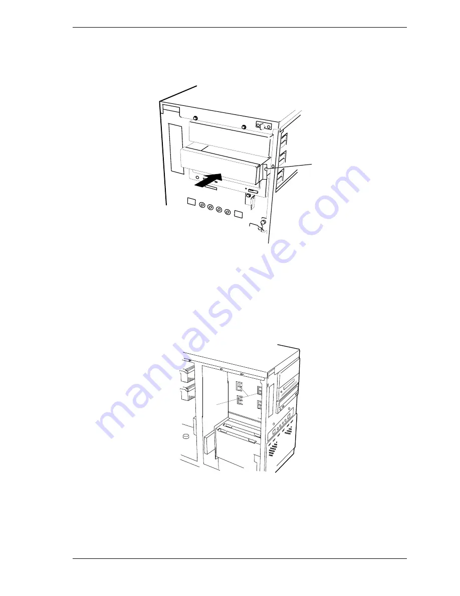
Install the media device into the bay as follows:

!


Move any cables in the bay out of the way.

!


Align the rails on the media device with the supports in the bay.

A

Figure 4-30. Installing a Removable Media Device

!


Slide the device into the bay until the right slide rail is against the system
cabinet. See Figure 4-30, A.

11. 

Secure the right side of the device to the system with the screw supplied.
See Figure 4-30, A.

12. 

Secure the left side of the device to the device bay with two screws supplied.
See Figure 4-31, A.

A

Figure 4-31. Securing a Removable Media Device

13. 

Connect the interface and power cable to the device.

14. 

Replace the left side panel and close the front panel.

15. 

Plug in the system power cord, and power on the system.

Summary of Contents for Express5800 120Ld

Page 1: ...U s e r s G u i d e EXPRESS5800 120Ld...

Page 2: ...xxx...

Page 3: ...U s e r s G u i d e EXPRESS5800 120Ld...

Page 4: ...tors such as system configuration customer data and operator control Since implementation by customers of each product may vary the suitability of specific product configurations and applications must...

Page 5: ...ller 1 12 The keyboard and mouse controller is PS 2 compatible 1 12 Network Controller 1 12 SCSI Controller 1 13 Video Controller 1 13 Peripheral Controller 1 13 Serial Ports 1 13 Parallel Port 1 13 E...

Page 6: ...nu 3 10 Numlock Submenu 3 11 Security Menu 3 12 System Hardware Menu 3 13 Thermal Sensor Submenu 3 13 Wake On Event Submenu 3 13 Console Redirection Submenu 3 14 Boot Menu 3 14 Boot Device Priority Su...

Page 7: ...ing 5 6 Troubleshooting Guide 5 6 Preparing the System for Diagnostic Testing 5 6 Monitoring POST 5 7 Verifying Proper Operation of Key System Indicators 5 8 Confirming Loading of the Operating System...

Page 8: ...and Disconnecting the Server B 12 Using a Remote Drive B 13 Setting and Clearing Server Pause B 13 Recovering from an SOS B 14 Alerting ESMPROTM B 15 Dialog Boxes B 15 Select a Server Dialog Box B 15...

Page 9: ...This chapter also provides information on system board jumper settings Chapter 4 Upgrades and Options provides you with instructions for upgrading your system with an additional processor optional me...

Page 10: ...oss of life CAUTION Cautions indicate situations that can damage the system hardware or software Note Notes give important information about the material being described Names of keyboard keys are pri...

Page 11: ...released Getting Started Sheet The Getting Started Sheet provides several easy to follow steps to become familiar with your server documentation and to complete your installation successfully Network...

Page 12: ...ng the procedures in this manual make sure that your system is powered off and unplug the AC power cord from the back of the chassis Failure to disconnect power before opening your system can result i...

Page 13: ...he external ports Remote Earths To prevent electrical shock connect all local individual office computers and computer support equipment to the same electrical circuit of the building wiring If you ar...

Page 14: ...ystem warm or cool to room temperature before using it Keep the system away from magnetic forces Keep the system dry Do not wash the system with a wet cloth or pour fluid into it Protect the system fr...

Page 15: ...1 System Overview Overview System Chassis Power Supply Peripheral Bays SAF TE Logic System Board Features AC Link Mode Remote Power On Wake On LAN Function System Security...

Page 16: ...ent for many server market applications These range from large corporations supporting remote offices to small companies looking to obtain basic connectivity capability such as file and print services...

Page 17: ...er features the following major components Single or dual high performance Pentium III processors packaged in Single Edge Contact Cartridge Version 2 SECC2 64 MB to 4 GB of memory using up to four DIM...

Page 18: ...system only and an interlock switch on the side cover Hot Swap SCSI Hard Drive Bays Six hot swap 1 0 inch SCSI hard disk drive bays accessible from the front of the chassis which can be swapped in or...

Page 19: ...components are shown in the following illustrations F G A B C D E H I J A Removable Media Bay B SCSI Hard Disk Drive Bays C SCSI Hard Disk Drive Bay Fan D Front Input Fan E System Board F Rear Exhaust...

Page 20: ...r drives or six hot swap drive bays for mounting up to six drives in easily removable drive carriers Note The hot swap SCSI hard disk drive bays contain a hot swap back plane that require an 80 pin si...

Page 21: ...64 bit 33MHz PCI slots for add in boards G Power switch and Interlock switch connector X 32 bit 33MHz PCI slots for add in boards H Not used Y PCI ISA shared slot for add in board I Management interfa...

Page 22: ...ximum of 133 MHz The second level cache is located on the substrate of the processor cartridge The cache includes burst pipelined synchronous static RAM BSRAM System Memory The system board contains f...

Page 23: ...pport bus speeds up to 66 MHz The third connector slot PCI 3 supports a bus speed of up to 33 MHz Note The bus speed for the two 66 MHz PCI connector slots PCI 1 or PCI 2 is decreased to 33 MHz if a P...

Page 24: ...ith an ISA connector ISA 1 PCI features Bus speed up to 33 MHz 32 bit memory addressing 5 V signaling environment Burst transfers up to a peak of 132 MB s 8 16 or 32 bit data transfers Plug and Play r...

Page 25: ...gure 1 8 Shared ISA PCI Connector Slot Real Time Clock Calendar The real time clock provides system clock calendar information stored in a non volatile memory NVRAM The real time clock battery provide...

Page 26: ...r As a PCI bus master the controller can burst data at up to 132 MB sec The controller contains two receive and transmit FIFO buffers that prevent data overruns or underruns while waiting for access t...

Page 27: ...y of 100 Hz Peripheral Controller The advanced integrated peripheral controller supports two serial ports two universal serial ports one parallel port diskette drive PS 2 compatible keyboard and mouse...

Page 28: ...ence in the nonvolatile System Event Log SEL The events being monitored include overtemperature and overvoltage conditions fan failure or chassis intrusion To enable accurate monitoring the BMC mainta...

Page 29: ...AC power is disconnected is the system completely off The sleep states are defined as follows s0 Normal running state s1 Processor sleep state No context will be lost in this state and the processor...

Page 30: ...omputer chassis The computer chassis includes an interlock switch on the side cover When any these covers are opened the switch transmits an alarm signal to the system board where server management so...

Page 31: ...System Making Connections Setting the Line Voltage Connecting the Power Cord Powering On Your System Overview This chapter describes how to select a site unpack the system make cable connections and p...

Page 32: ...nd well ventilated Front and rear ventilating openings kept free of obstructions Away from sources of heat vibration or physical shock Isolated from strong electromagnetic fields and electrical noise...

Page 33: ...tage is removed only when the power cords are unplugged Avoid excessive vibration and shock Dropping an electronic component can cause serious damage Do not disconnect or remove parts other than those...

Page 34: ...configuration for the rack cabinet you should consider the length of the cables that interconnect system components 2 Locate the two support brackets D Using four self tapping screws E supplied with t...

Page 35: ...p the System 2 5 A Rear vertical mounting rail B Front vertical mounting rail C Four caged nuts D Two support brackets E Eight self tapping screws Figure 2 1 Assembling the Support Brackets in the Rac...

Page 36: ...hen lifting and assembling the rack mount server unit into a rack cabinet 5 Secure the front bezel to the rack cabinet s front vertical mounting rails B using the four screws E and plastic washers D p...

Page 37: ...section describes the tower based system controls switches and indicators and connectors which are identical for the rack mount system Front View with Front Door Closed Figure 2 3 shows the location...

Page 38: ...ure 2 4 and open the front door of the cabinet as follows tower based system only 1 If the front door is locked unlock it 2 Grasp the indentation located on the right edge of the front door and pull t...

Page 39: ...r off F DC Power ON OFF LED When green power is present in system When off power is turned off power source is disrupted or system is in the sleep mode See Table 2 1 for a list and description of the...

Page 40: ...2 H DC power ON OFF Button Press to turn system DC power on or off I DC Power ON OFF LED When green power is present in system When off power is turned off power source is disrupted or system is in t...

Page 41: ...compatible 6 pin mini DIN connector Purple H Mouse port PS 2 compatible 6 pin mini DIN connector Green I SVGA connector SVGA monitor 15 pin connector Blue J LAN connector RJ 45 Ethernet connector K A...

Page 42: ...disk drive failure Check disk drive status LEDs Off System in Normal mode None required normal Sleep Status Amber System power saving sleep mode Press Sleep button to return to Normal mode Hot swap c...

Page 43: ...r to Chapter 3 Configuring Your System of this User s Guide Refer to the previous figure Rear Features and Controls and connect your keyboard monitor and mouse Connect any external peripheral devices...

Page 44: ...or the power supply is correct To use the system with line source voltages between 200 and 240 VAC the line voltage selector switch on the power supply must be set to 230 If you set the switch to the...

Page 45: ...s not compatible with the AC wall outlet in your region obtain a suitable power cord that meets the following criteria The power cord must be rated for the available AC voltage and have a current rati...

Page 46: ...is lit If it is not lit ensure the ac power cord is connected to a functional ac power source After a few seconds your system begins the internal Power On Self Tests POST POST automatically checks the...

Page 47: ...3 Configuring Your System Configuring Your System BIOS Setup Utility Adaptec SCSI Utility Configuring the RAID Controller Configuring System Board Jumpers...

Page 48: ...your system or to perform a SCSI disk format or verify disk operation on the SCSI disk drives The Adaptec Configuration Utility is also used to configure any SCSI removable media devices installed in...

Page 49: ...Advanced Use this menu for setting the Advanced Features available on your system Security Use this menu to set User and Supervisor Passwords and the Backup and Virus Check reminders System Hardware U...

Page 50: ...dow PAGE UP or PAGE DOWN Move cursor to next or previous page F5 or Select the previous value for the field F6 or or SPACE Select the next value for the field F9 Load default configuration values for...

Page 51: ...the total capacity of the extended memory Language English US French German Spanish Italian Selects which language BIOS displays Note This feature immediately changes to the language BIOS selected BIO...

Page 52: ...Submenu Peripheral Configuration Refer to Peripheral Reconfiguration Submenu Monitoring Configuration Refer to Monitoring Configuration Submenu It sets POST Monitoring and Boot Monitoring PCI Device...

Page 53: ...isables or enables RomPilot support The Boot time diagnostic screen is enabled if RomPilot is enabled See Appendix B for more details Memory Reconfiguration Submenu Feature Choices or Display Only Des...

Page 54: ...ts the base address and interrupt IRQ for the Parallel port Parallel Mode Output only Bi directional EPP ECP DMA1 ECP DMA3 Selects the parallel port operation mode Diskette Controller Disabled Enabled...

Page 55: ...ady in use by ISA devices Use Auto only if no ISA legacy cards are installed Option ROM Submenu Feature Choices or Display Only Description Your Setting Onboard SCSI Enabled Disabled Disables Enables...

Page 56: ...A 3 DMA 4 DMA 5 DMA 6 DMA 7 Reserves specific DMA channels for use by legacy ISA devices DMA Channel 2 Same as above I O Port Address 1 0 Select I O port base address Reserved 16 byte 110 3F0 0 None I...

Page 57: ...Auto On OFF Selects the power on state for Numlock Key Click Disabled Enabled Disables or enables keyclick Keyboard Auto repeat Rate 2 sec 6 sec 10 sec 13 3 sec 18 5 sec 21 8 sec 26 7 sec 30 sec Selec...

Page 58: ...sed the user is prompted for a password press ESC key to abort Once set this can be disabled by setting it to a null string or by clearing password jumper on system board refer to System Board Jumpers...

Page 59: ...lay System Event Log Not Cleared Console Redirection Additional setup menu to configure console The Boot Time diagnostic screen is enabled if redirection is enabled Thermal Sensor Submenu Feature Choi...

Page 60: ...flow control Console Connection Direct Via Modem Indicate whether the console is connected directly to the system or a modem is used to connect Boot Menu Use the up or down arrow keys to select a devi...

Page 61: ...u must select one of the items from the menu or menu bar to exit Exit Menu Choices Description Save Changes and Exit Exits System Setup after saving all changes to CMOS Exit Without Saving Changes Exi...

Page 62: ...y starts When the Adaptec SCSI Utility detects more than one AIC 78xx host adapter it displays a selection menu listing the bus and device number of each adapter When the selection menu appears select...

Page 63: ...to these settings Table 3 1 Adaptec SCSI Utility Setup Configurations OPTION RECOMMENDED SETTING OR DISPLAY ONLY YOUR CONFIGURATION SCSI Bus Interface Definitions Host Adapter SCSI ID 7 SCSI Parity C...

Page 64: ...t Adapter BIOS Configuration Utility Reserves BIOS Space Enabled 1 Domain Validation Enabled Support Removable Disks Under BIOS as Fixed Disks Disabled 1 2 BIOS Support for Int13 Extensions Enabled 1...

Page 65: ...AID 5 with a standby drive The array consists of three ON LINE drives and one STANDBY drive The standby replacement drive or hot spare is one of the most important features RAID provides to achieve au...

Page 66: ...ocedures in this section CAUTION Electrostatic discharge ESD can damage the system board Modify the system board only at an ESD workstation Otherwise wear an antistatic wrist strap attached to chassis...

Page 67: ...tion make sure that your system is powered off and unplug the AC power cords from the back of the chassis Failure to disconnect power before moving the jumpers can result in personal injury and equipm...

Page 68: ...ble of jumper block 1M5 Refer to the previous illustration System Board Jumpers to find the location of this jumper 4 Power on the system and while waiting for POST to complete press the F2 key to ent...

Page 69: ...on off switch on the front panel and your system powering down This is normal system operation and is required by the server management logic CAUTION Operating your system with the side panels remove...

Page 70: ...of your system all installed options and any other pertinent information specific to your system You will need this information when configuring your system Opening and Removing the Front Door You mus...

Page 71: ...sengaged from their mounting holes on the front of the system Figure 4 2 Removing the Front Door To install the front door 1 Position the front door so the mounting pins of the front door are aligned...

Page 72: ...r the system is set up you must first power off the system and all external devices and then Unplug the system power cord To remove the left side panel 1 Power off the system and ensure it is disconne...

Page 73: ...ng fingers behind the side panel 5 Pull the side panel out and away from the chassis Installing Side Panels 1 Before replacing the side panel make sure no tools or loose parts have been left inside th...

Page 74: ...ground Replacing the Real time Clock Battery You may need to replace the real time clock battery because of its life span The battery Vendor Part CR2450 is a commodity part available through many vend...

Page 75: ...nt under the plastic tab on the San in plastic retainer 6 Gently push down on the screwdriver to lift the battery Figure 4 5B 7 Remove the battery from its socket Figure 4 5C 8 Dispose of the battery...

Page 76: ...a back cover The primary processor connector is shown at Figure 4 6 A in the illustration below The secondary processor connector is shown at Figure 4 6 B CAUTION Electrostatic discharge ESD can dama...

Page 77: ...d you are replacing it leave the terminator board intact in the empty secondary processor connector Remove the processor you want to replace 5 If your system has two processors and you are replacing o...

Page 78: ...e system DIMMs The system board contains four DIMM sockets labeled 1 through 4 Figure 4 8 Each socket can hold a single 72 bit DIMM module with 64MB 128MB 256MB 512MB or 1GB of memory When all four so...

Page 79: ...ly by the edges remove it from its antistatic package 4 Position the DIMM so that the two notches in the bottom edge of the DIMM align with the keyed socket See Figure 4 9 Figure 4 9 Inserting Memory...

Page 80: ...the front door and remove the left side panel as described earlier in this chapter 3 Gently push the plastic ejector levers out and down to eject a DIMM from its socket See Figure 4 9 4 Hold the DIMM...

Page 81: ...e configured around the manually configured adapters without causing any resource conflicts ISA adapters can be Plug and Play ISA adapters that are not Plug and Play must be manually configured follow...

Page 82: ...comes with the option board 7 Refer to the documentation accompanying the option board for information on whether the board is a PCI or ISA board Note If you are adding a non Plug and Play Legacy ISA...

Page 83: ...if they are needed to the installed option board 12 Replace the left side panel and close the front panel 13 Plug in the system power cord and power on the system Removing an Option Board Note Expans...

Page 84: ...power cord and power on the system 9 If you removed a non Plug and Play ISA option board run the BIOS Setup utility press F2 at the startup screen to configure the system as described in the Configur...

Page 85: ...k device consider the following CAUTION Do not hot swap a non LVD disk drive into a LVD disk drive only system for it may cause data corruption The only way a non LVD disk drive can be used with an al...

Page 86: ...ual SCSI drive fault LED yellow light is on steadily this indicates that the drive has been flagged as faulty by the RAID host controller See Figure 4 14 A Follow the procedure described in this secti...

Page 87: ...two thumb lock screws counter clockwise see Figure 4 14 B 3 If swapping a hard disk drive remove the drive and its carrier from the SCSI hard disk drive bay by performing the following procedures CAUT...

Page 88: ...ial numbers in the equipment log 8 Install the replacement drive onto the drive carrier Place the drive on the carrier with its connector facing the rear of the carrier Turn the drive and carrier over...

Page 89: ...ng a Disk Carrier into the Disk Bay Right Wrong Figure 4 18 Locking the Disk Carrier 10 Close and secure the EMI metal panel 11 Close the front door on the system If necessary configure the system as...

Page 90: ...st use the industry standard 68 pin Wide SCSI interface connector Note To order a hard disk drive contact your sales representative or dealer If installing new drives follow an installation scheme sta...

Page 91: ...nsure it is disconnected from the AC power source 2 Open the front door as described earlier in this chapter 3 Remove the left and right side panel as described earlier in this chapter 4 Tag and disco...

Page 92: ...of the left side of the chassis See Figure 4 21 Figure 4 21 Removing the Drive Bay out of the Chassis 10 If you are installing a new or replacement hard disk drive remove the drive from its protectiv...

Page 93: ...n Step 6 See Figure 4 20 C and D 16 Install the mounting screws that secure the drive bay to the right side of the chassis See Figure 4 20 A and B 17 Install the mounting screw that secures the drive...

Page 94: ...ive address assignment is 2 The SCSI termination resistors must be installed in the last SCSI drive of the daisy chain cabling If the SCSI tape drive is your only SCSI device on the SCSI controller B...

Page 95: ...movable media drive cage See Figure 4 25 Figure 4 25 Removing the Diskette Assembly 7 Remove the diskette and mounting bracket from the system and place the assembly on an antistatic surface 8 If you...

Page 96: ...on exposure 1 Power off the system and ensure it is disconnected from the AC power source 2 Open the front door as described earlier in this chapter 3 Remove the left side panel as described earlier i...

Page 97: ...r in the equipment log 8 Set any drive jumpers or switches before you install the drive See the documentation that comes with the device for jumper or switch information Note If the drive comes with d...

Page 98: ...right slide rail is against the system cabinet See Figure 4 30 A 11 Secure the right side of the device to the system with the screw supplied See Figure 4 30 A 12 Secure the left side of the device to...

Page 99: ...documentation may result in hazardous radiation exposure 1 Power off the system and ensure it is disconnected from the AC power source 2 Open the front door as described earlier in this chapter 3 Remo...

Page 100: ...of the device bay and set it down on an antistatic surface 8 Remove the screws securing the right side rail to the device See Figure 4 29 9 To install a replacement device follow the procedures in Ins...

Page 101: ......

Page 102: ...Static Precautions Troubleshooting Checklists Diagnostic Testing Specific Problems and Corrective Actions Problems with the Network Plug and Play Installation Tips BIOS User s Information How to Iden...

Page 103: ...AC outlet Before doing the procedures in this manual make sure that your system is powered off and unplug the AC power cords from the back of the chassis Failure to disconnect power before opening yo...

Page 104: ...rd Are all jumpers and switch settings on option boards and peripheral devices correct If applicable ensure that there are no conflicts for example two option boards sharing the same interrupt Are the...

Page 105: ...not work Obtain an authorized copy of the software If you are running the software from a diskette is it a good copy If you are running the software from a hard disk drive is the software correctly i...

Page 106: ...ed If the problem recurs you may need to reformat the hard disk drive The hard disk drive the drive controller or the system board may be defective If the problems are intermittent there may be a loos...

Page 107: ...are the system for diagnostic testing perform the following Note Before disconnecting any peripheral cables from the system turn off the system and any external peripheral devices Failure to do so can...

Page 108: ...e there is a problem with the display it emits a series of long and short beeps Write down any beep code emitted This information is useful to your service representative Refer to the BIOS User s Info...

Page 109: ...System Indicators As POST determines the system configuration it tests for the presence of each mass storage device installed in the system As each device is checked its activity indicator should turn...

Page 110: ...ctivity LED does not light CD ROM drive activity LED does not light Problems with application software The startup prompt Press F2 key if you want to run Setup does not appear on the screen The bootab...

Page 111: ...controls on the video monitor properly adjusted Are the video monitor switch settings correct Is the video monitor signal cable properly installed Is the onboard video controller enabled If you are us...

Page 112: ...functioning the power supply has probably failed Contact your service representative for assistance Diskette Drive Activity LED Does Not Light Check the following Are the diskette drive s power and s...

Page 113: ...e software vendor s customer service representative for assistance Bootable CD ROM Is Not Detected Check the following Is the BIOS set to allow the CD ROM to be the first bootable device Check your BI...

Page 114: ...an be used to adjust the interrupt numbers for PCI devices For certain drivers it may be necessary to alter settings so that interrupts are not shared BIOS User s Information This section describes th...

Page 115: ...re Fixed Disk 0210 Stuck Key 0211 Keyboard error 0212 Keyboard Controller Failed 0213 Keyboard locked Unlock key switch 0220 Monitor type does not match CMOS Run SETUP 0230 System RAM Failed at offset...

Page 116: ...ure out of range 0B74 The error occurred during voltage sensor reading 0B75 System Voltage out of range 0B7C The error occurred during fan sensor reading 0B80 BMC Memory Test Failed 0B81 BMC Firmware...

Page 117: ...ts error number xx None Expansion ROM not initialized None Invalid System Configuration Data None System Configuration Data Read error None Resource Conflict None System Configuration Data Write Sourc...

Page 118: ...yte Error Memory data signal failure low Change DIMM or M B 1 4 1 1 DRAM Test high byte Error Memory data signal failure high Change DIMM or M B 1 4 3 3 All Memory Group Errors 2 1 2 3 BIOS ROM Copy W...

Page 119: ...setting in your system BMC Revision Level Identification During system Power On Self Test POST which runs automatically when your system is powered on system diagnostics are run Following the memory...

Page 120: ...A System Cabling System Cabling Before You Begin Static Precautions Standard Configuration RAID Configuration...

Page 121: ...re doing the procedures in this manual make sure that your system is powered off and unplug the AC power cords from the back of the chassis Failure to disconnect power before opening your system can r...

Page 122: ...t SCSI devices in the removable media bays A 68 pin to 50 pin converter is also available to be used when installing SCSI narrow devices A 3 5 inch diskette drive is also installed in all systems and...

Page 123: ...nnector 68 pin C Diskette drive K Ultra 160 M SCSI interface cable D IDE connector L Six SCSI disk drive bays E IDE interface cable M SCSI backplane F IDE CD ROM drive N SCSI hard disk drives G Ultra2...

Page 124: ...ystem board G Ultra2 SCSI connector 68 pin Figure A 2 Standard System Cable Configuration Standard Drive Bay RAID Configuration The RAID options available for your system provide your system with the...

Page 125: ...drive K Ultra 160 M SCSI connector 68 pin D IDE connector L Ultra 160 M SCSI interface cable E IDE interface cable M Six SCSI disk drive bays F IDE CD ROM drive N SCSI hard disk drives G Ultra2 SCSI...

Page 126: ...controller C Diskette drive K Ultra 160 M SCSI connector 68 pin D IDE connector L Ultra 160 M SCSI interface cable E IDE interface cable M Four SCSI disk drives F IDE CD ROM drive N System board G Ul...

Page 127: ......

Page 128: ...B Management Workstation Application Overview MWA System Requirements Installing MWA MWA Main Window Using MWA Dialog Boxes Troubleshooting...

Page 129: ...This function enables you to see the screen of a server from the console of the management PC and to key in data to the server from the keyboard of the management PC Remote drive access This function...

Page 130: ...file can be used instead of a floppy disk as a remote drive for a server A server can also be booted from a floppy disk on the management PC When the remote drive function is in use RD is displayed a...

Page 131: ...he management PC Configure and register SG information within MWA at the management PC Creating a Server System Generation Diskette SG For the management PC to connect with a server server system gene...

Page 132: ...n used between server SMC and management PC MWA community name for SNMP trap Default value is public Magic Number SMC supported servers Enter code key that is used between server SMC and management PC...

Page 133: ...agement PC perform the following procedure 1 Start Windows95 Windows 98 or Windows NT on the management PC 2 Insert the EXPRESSBUILDER CD into the PC CD ROM drive 3 Using Explorer execute setup exe in...

Page 134: ...lows Open The Open command opens a server window for a specified server Connect The Connect command connects a current server Disconnect The Disconnect command disconnects a current server Pause POST...

Page 135: ...he server list SG information for only one server can be saved on a floppy disk because the server SG information for all files is saved under the same name Properties displays or set properties for t...

Page 136: ...tton is selected the Delete Logged Messages dialog box displays The operator can delete all or part of the log When the History Log dialog box is open a check mark appears next to the menu item Reset...

Page 137: ...e and so on Window Cascade command arranges the opened windows in an overlapping fashion Tile arranges the opened windows in a non overlapping fashion Arrange Icons arranges icons for minimized window...

Page 138: ...current server is executing POST To resume POST select the Go to End of POST command then select Go MWA mode command or the Go No MWA mode command Go to End of POST command pauses the server at the en...

Page 139: ...s connected the remote control function displays the server screen in the server window at the management PC Most MWA functions can be executed only when a server is connected Connect to a server as f...

Page 140: ...a file name Note If Read Only is checked a FD image file can be used in some servers Note The Server must be reset after a remote drive is used in the server Setting and Clearing Server Pause MWA can...

Page 141: ...OS message is received MWA opens an SOS Receive dialog box to display the SMC event log and other information The server recovery method depends on the recovery mode of each server Automatic recovery...

Page 142: ...OST stalled SMI handler alarm SMI handler stall Not supported by some server models Dialog Boxes Select a Server Dialog Box The Select a server dialog box displays a list of SG registered servers on M...

Page 143: ...d Default Server Properties Dialog Box From the Default Server Properties dialog box you can view and set basic properties of all servers If Use Default Settings in the Server Properties dialog box is...

Page 144: ...m the history log Delete history timed at xx xx xx xx xx xx and earlier If a logged message is selected in the History Log dialog box a condition for deletion can be set for messages of the same date...

Page 145: ...ed data Read Data from Server The present data of the current server is acquired and displayed The Save As button is used to save the acquired data in a file Temporary Change to Remote Drive Dialog Bo...

Page 146: ...ialog box displays The server cannot be controlled from MWA Message The dialog box displays the SOS message received from a server on the first line The display box also displays the SMC event log of...

Page 147: ...lem MWA cannot be operated after the reset command was executed Probable Cause When some reset commands are issued MWA waits for a response and cannot perform other operations Wait for a while Problem...

Page 148: ...S program is activated in English mode the server displays corrupted characters Probable Cause If MS DOS in the server is in English mode MWA remote console correctly displays messages from the MS DOS...

Page 149: ...B 22 Management Workstation Application...

Page 150: ...C System Status Hardware Support Information...

Page 151: ...component Monitoring capability relates to how the software component interacts with system hardware ESMPRO interacts with all hardware components See Figure System Chassis Right Side View under Syst...

Page 152: ...of data for safe keeping The data is copied from computer memory or disk to a floppy disk magnetic tape or other media backup battery The battery in your computer that maintains the real time clock a...

Page 153: ...OM drive A type of mass storage device that reads information from a compact disk Centronics port An industry standard parallel port See also parallel port CGA Color Graphics Adapter A type of video d...

Page 154: ...software program that a computer must use to recognize and operate certain hardware such as a mouse or a video monitor disk drive A device that stores data on a hard or floppy disk A floppy disk driv...

Page 155: ...nd ROM expansion slot See backplane slot extended memory The protected memory above 1M that is directly accessible by the microprocessor through certain utilities and operating systems F fault resilie...

Page 156: ...e of hard disk drive with the control circuitry located inside the disk drive rather than on a drive controller card interface A connection between the computer and a peripheral device that enables th...

Page 157: ...uter that stores data and programs See also EMS extended memory RAM and ROM microprocessor The integrated circuit that processes data and controls the basic functions of the computer modem A device us...

Page 158: ...bus controllers that processes and communicates 32 bits of data at a time This microprocessor also contains power management capabilities peripheral A device connected to and controlled by the compute...

Page 159: ...tem management events The information stored includes the name of the event the date and time the event occurred and data pertinent to the event Event data may include POST error codes that reflect ha...

Page 160: ...SI interface based on Ultra3 SCSI technology This interface features data transfer speeds up to 160MB second double edge clocking cyclical redundancy checking CRC providing higher levels of data relia...

Page 161: ...10 Glossary...

Page 162: ...nents added to the system such as a power supply hard disk drives add in boards or printers Record the model and serial numbers of the unit and system baseboard The model and serial numbers of the sys...

Page 163: ...M Slot 2 DIMM Slot 3 DIMM Slot 4 Modem Diskette Drive A Tape Drive 1 Tape Drive 2 CD ROM Drive 1 Hard Disk Drive 1 Hard Disk Drive 2 Hard Disk Drive 3 Hard Disk Drive 4 Hard Disk Drive 5 Hard Disk Dri...

Page 164: ...3 22 password 3 22 recovery boot 3 22 L LAN status 2 13 Lithium backup battery installing 4 8 M Management workstation application B 2 dialog boxes B 15 installing B 4 main window B 7 system requireme...

Page 165: ...on 1 4 1 16 Setup Advanced menu 3 6 Boot menu 3 14 Exit menu 3 15 Integrated Peripheral Configuration menu 3 8 Security menu contents 3 12 Switches alarm 1 4 1 16 System board configuration jumpers 3...

Page 166: ...xx...

Page 167: ...456 01530 000...

Reviews: