Setting Up the System 2-9
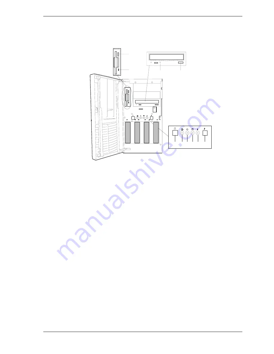
Front View (Non-Hot-Swap SCSI Drive Bays)
Figure 2-5 shows the location of the front system controls and indicators on a
system that includes the standard SCSI disk drive bays.
A
B
C
D
H I
J
E
F G
A.
Eject button, 3 ½-inch diskette drive
Press to eject diskette.
B.
Activity light, 3 ½-inch diskette drive
When lit, diskette is in use.
C.
Activity light, CD-ROM reader
When lit, CD-ROM reader is in use.
D.
Load/eject button, CD-ROM reader
Press to load CD and eject CD.
E.
DC power ON/OFF Button
Press to turn system DC power on or off.
F.
DC Power ON/OFF LED
When green, power is present in system. When
off, power is turned off, power source is
disrupted, or system is in the sleep mode. See
Table 2-1 for a list and description of the system
LEDs.
G.
Intrusion LED
When OFF, the system is OK. See Table 2-1 for
a list and description of the system LEDs.
H.
Disk Fault LED
Non-functional on systems that include the
standard SCSI disk drive bays.
I.
Sleep Status LED
When lit, system is in Sleep Mode. See Table
2-1 for a list and description of the system LEDs.
J.
Sleep Button
Press to enter power saving (sleep) mode. Press
again to enter normal mode of operation. This
function requires a corresponding operating
system.
Figure 2-6. Front System Features and Controls (Non-Hot-Swap Bays)
Summary of Contents for Express5800 120Ld
Page 1: ...U s e r s G u i d e EXPRESS5800 120Ld...
Page 2: ...xxx...
Page 3: ...U s e r s G u i d e EXPRESS5800 120Ld...
Page 101: ......
Page 127: ......
Page 149: ...B 22 Management Workstation Application...
Page 150: ...C System Status Hardware Support Information...
Page 161: ...10 Glossary...
Page 166: ...xx...
Page 167: ...456 01530 000...


