background image


BenchMike Pro Instruction Handbook: Installation 


2-5


2.2.3 

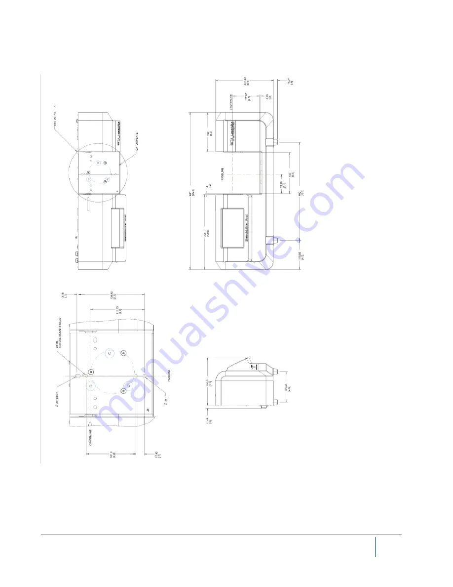
BenchMike Pro Model 2050 Outline Drawing 


NOTE: Dimensions are in millimeters (inches). 

NOTE: Mount the universal mounting plate with the -20 in the lower left corner (as seen looking downward from 
the operator’s position) of the BenchMike Pro’s measurement area. 

Summary of Contents for BenchMike Pro 2025

Page 1: ...eter Instruction Handbook NDC Technologies 8001 Technology Blvd Dayton Ohio 45424 U S A 2019 NDC Technologies 2017 NDC TechnologiesNDC Main Phone 1 937 233 9935 General Fax 1 937 233 7284 www ndc com betalasermike BETA LaserMike Products ...

Page 2: ...ereto and to any article disclosed therein except to the extent rights are expressly granted to others The fore going does not apply to vendor proprietary parts In line with NDC s policy of continuous improvement the information contained in this document may change to allow the introduction of design improvements BenchMike Pro Instruction Handbook Part Number MAN EN5008 0092 Revision E Language E...

Page 3: ...ccess information in our on line knowledge database You can browse the myNDC site or create a myNDC account To create a myNDC account click the Log in or Sign up button After creating the account you will be immediately logged in To log in on subsequent visits to myNDC click the Log in or Sign up button en ter your user name and password and then click Log in To submit an RMA click on the RMA Requ...

Page 4: ......

Page 5: ...including Infrared Xray and Nucleonic Sensors Americas 1 626 939 3855 Asia Pacific Japan 81 0 3 3255 8157 All other countries 44 1621 852244 Select option 3 to be connected to the service team China 86 21 61133609 EMEA Europe Middle East Africa Germany 0800 1123194 France 0810 600 400 Italy 39 0331 454 207 All other countries English speaking 44 1621 852244 Please select option 3 to be connected t...

Page 6: ... 21 61133609 EMEA Europe Middle East Africa Germany 0800 1123194 France 0810 600 400 Italy 39 0331 454 207 All other countries English speaking 44 1621 852244 Please select option 3 to be connected to the service team NDC Metals Systems including AccuRay and IRM brands NDC Metals Systems including AccuRay and IRM brands Americas North America 1 626 939 3855 South America 32 4 239 90 10 Asia Pacifi...

Page 7: ...laser diode or gas laser and of the entire BenchMike Pro is relatively low The laser beam will not harm your skin and your eyes are protected by a natural aversion response that will cause you to blink or look away However the laser light emitted from the BenchMike Pro should be treated with caution and common sense Do not attempt to look into the BenchMike Pro and avoid staring at reflections of ...

Page 8: ...y features incorporated into the design of the instrument The following figures show the identification and advisory labels on the BenchMike Pro Front View Model 2025 DB 9 FEMALE SERIAL 1 LASER SAFETY LABEL SERIAL TAG ETHERNET DB 25 MALE I O BNC DB 25 FEMALE FIXTURE USB A PRINTER USB B SERIAL Aperture label Scanning laser beam Laser safety label back panel Laser emission LED ...

Page 9: ... is operated in a commercial environment This equipment generates uses and can radiate radio frequency energy and if not installed and used in accordance with the instruction manual may cause harmful interference to radio communications Operation of the equipment in a residential area is likely to cause harmful interference in which case the user will be required to correct the interference at his...

Page 10: ...6 1 7 LASER SAFETY 1 7 1 7 1 Output Beam Data 1 7 1 7 2 Warning Information 1 7 2 INSTALLATION 2 1 2 1 INSTRUCTIONS 2 1 2 1 1 Power 2 1 2 1 2 Lifting 2 1 2 1 3 Location 2 1 2 1 4 Ventilation Requirements 2 1 2 1 5 Equipment Maintenance 2 1 2 1 6 Caution Symbol 2 2 2 2 DRAWINGS 2 2 2 2 1 BenchMike Pro Model 2025 Outline Drawing 2 3 2 2 2 BenchMike Pro Model 2025 Connector Drawing 2 4 2 2 3 BenchMik...

Page 11: ...cedure 2 23 3 WORKHOLDING FIXTURES 3 1 3 1 ERROR SIGNALS 3 1 3 2 INTELLIGENT AND NON INTELLIGENT FIXTURES 3 1 3 2 1 Non Intelligent Fixture Linear Slide Position 3 1 3 2 2 Intelligent Fixture Rotary Linear Fixture Position 3 2 3 3 DESCRIPTION OF FIXTURES 3 2 3 3 1 General Purpose Fixed V Block Fixture 3 2 3 3 2 Universal Slide Fixture 3 3 3 3 3 Digital Readout DRO Slide Fixture 3 7 4 SETUP 4 1 4 1...

Page 12: ...ession Editor 4 28 4 11 2 Fixtures Menu 4 28 4 11 3 Measurement Type 4 32 4 11 4 Measurement Method 4 34 4 11 5 Averaging Mode 4 34 4 11 6 Custom Mode 4 34 4 11 7 Nominal Limits Tolerance Setup 4 35 4 11 8 Floating Nominal 4 35 4 11 9 Master Measurement 4 36 4 12 DATA FUNCTIONS 4 37 4 13 SAVE FUNCTION 4 41 4 14 STATUS MENUS 4 42 4 15 SECURITY SETUP 4 45 4 15 1 Entering the System Password 4 46 4 1...

Page 13: ... the Wrapper 6 3 6 2 3 Messages to the BenchMike Pro with the Wrapper 6 3 6 2 4 Messages from the BenchMike Pro with the Wrapper 6 4 6 2 5 Prefix Setting 6 9 6 3 COMMAND DESCRIPTIONS 6 10 6 3 1 Configure Settings 6 10 6 3 2 Getting Help 6 19 6 3 3 Performing Measurements 6 19 6 3 4 Checking System Status and Configuring Libraries 6 21 6 4 TABLE OF COMMANDS 6 24 7 SERVICING YOUR EQUIPMENT 7 1 8 SPE...

Page 14: ......

Page 15: ...e types of optional BenchMike Pro equipment 1 2 1 Laser Beam Options There are wide beam options for all BenchMike Pro models which permit the measurement of rough surfaces A small spot size option is also available for the Model 2025 to measure small diameters and part features down to 0 001 inch 25 4 µm 1 2 2 Interfaces The following input and output interfaces are ordered as options to the stan...

Page 16: ...ore a certificate of calibration is issued each of the following procedures is performed at the factory External optics are cleaned Internal optics are cleaned Multiple mastered points are used to enhance accuracy Test points and power supply voltages are verified Optics are aligned Scan across test is performed to verify accuracy at several hundred points Repeatability test is performed to determ...

Page 17: ...ket around the display 1 5 Measuring a Product The BenchMike Pro measures a part by sweeping a beam of laser light across its measurement area Each sweep of the beam is called a scan The BenchMike Pro scans the part 100 times per second As the beam sweeps through the BenchMike Pro s measure ment area it is alternately blocked by the part or allowed to pass through to the receive side of the BenchM...

Page 18: ...ts with a cloth before measuring them Dust or contamination on the transmitter or receiver scan window will also produce incorrect measurements Follow the cleaning procedure de scribed later in this manual as part of a routine maintenance program Incorrectly placing the object in the measurement area will also produce incorrect measurements Place the measured object perpendicular to the scanning l...

Page 19: ...The drawings to the right show sample oscilloscope waveforms from the measurement of an opaque product and a transparent product For the opaque product the BenchMike Pro can easily determine the width of the product since the waveform drops sharply and rises sharply at the edges of the product For the transparent product however laser light passes through the product and the behavior of the light ...

Page 20: ...hough each scan received from the BenchMike Pro includes enough information to compute a size value ac curacy and repeatability are increased significantly if a number of scans are collected and averaged Scans can be taken of individual samples or continuous products as defined on the Measurement Setup page For individual samples an Averaging Rate value of 200 scans is typical For continuous produ...

Page 21: ...laser is present during operation If a problem occurs with the operation of the BenchMike Pro contact NDC Technologies Customer Service im mediately Only trained NDC Technologies service personnel should perform service operations on this product The use of controls or adjustments or the performance of procedures other than those specified in this manual may result in hazardous radiation exposure ...

Page 22: ......

Page 23: ... re ceives AC power through the supplied power cord connected to the rear panel inlet and it is turned on or off by the switch on the rear of the unit No special grounding connections are required except through the standard power cord provided Never bypass the safety ground on a power cord If this equipment is not installed and used according to the installation procedures the safety of this unit...

Page 24: ...ced by trained NDC Technologies personnel Failure to do so could result in physical injury damage to the product and or voiding of the warranty If you have any questions or problems please contact the NDC Technolo gies Customer Service Department 2 2 Drawings Use the following drawings to install the BenchMike Pro ...

Page 25: ... 1 BenchMike Pro Model 2025 Outline Drawing NOTE Dimensions are in millimeters inches NOTE mount the universal mounting plate with the 10 in the lower left corner as seen looking downward from the operator s position of the BenchMike Pro s measurement area ...

Page 26: ...ok Installation 2 2 2 BenchMike Pro Model 2025 Connector Drawing HEIGHT SCAN CENTER DB 9 FEMALE SERIAL 1 USB B FEMALE SERIAL USB LASER SAFETY LABEL SERIAL TAG PASSLINE ETHERNET USB A FEMALE PRINTER DB 25 MALE I O BNC DB 25 FEMALE FIXTURE ...

Page 27: ... 3 BenchMike Pro Model 2050 Outline Drawing NOTE Dimensions are in millimeters inches NOTE Mount the universal mounting plate with the 20 in the lower left corner as seen looking downward from the operator s position of the BenchMike Pro s measurement area ...

Page 28: ...tallation 2 2 4 BenchMike Pro Model 2050 Connector Drawing HEIGHT SCAN CENTER DB 9 FEMALE SERIAL 1 USB B FEMALE SERIAL USB LASER SAFETY LABEL SERIAL TAG PASSLINE ETHERNET RJ 45 SOCKET USB A FEMALE PRINTER DB 25 MALE I O BNC DB 25 FEMALE FIXTURE ...

Page 29: ...g for a straight through cable 2 3 2 Digital I O Connector The digital I O connector is a DB 25 connector The number of inputs and outputs on a BenchMike Pro will vary based on the number ordered by the customer There is a maximum of 8 software readable inputs supports level or transition detection and each input is pulled up to 5 V with a 4 7K resistor Alarm outputs are open collector with a maxi...

Page 30: ... 8 Alarm 3 Warning 9 Alarm 2 Warning 10 Alarm 1 Reject 11 5 Volts 12 Signal ground 13 Signal ground 14 N C 15 N C 16 Alarm 11 17 Alarm 12 18 Alarm 10 19 Alarm 9 20 Signal ground 21 Alarm 8 22 Alarm 7 23 Alarm 6 24 Alarm 5 25 12 Volts Non sequential order is intentional ...

Page 31: ...ro See the description of system functions for software configuration of digital inputs for details 2 3 4 Connecting to Digital Outputs with the BenchMike Pro 12V Supply Consult the diagram below to connect digital outputs via the BenchMike Pro s 12 V supply See the description of the system functions for software configuration of digital outputs for details ...

Page 32: ...RS232 interfaces and baud rates up to 38 4 Kbaud Handshaking protocol options are RTS CTS and none Data items available for transmission are from the Data menus Data format options such as Labels Headers Delimiters and Terminators as well as data flow options are available for selection from the Settings Serial Data Out Format menus DB 9 connectors are used for these ports 2 3 6 1 Serial Connector...

Page 33: ...d for either for a motor port OR open collector outputs Port 1 comes configured from the factory with a motor driver chip installed Port 1 and 2 come configured from the factory with motor driver chips installed Both ports can be used at the same time The BenchMike Pro is designed to control both a rotating fixture and a linear fixture at the same time The pin out for this DB 25 connector is shown...

Page 34: ...21 Quad encoder 1 input A 22 Quad encoder 1 input B 23 Quad encoder 2 input A 24 Quad encoder 2 input B 25 12 V 2 3 11 Connecting to a Quadrature Encoder Consult the diagram below to connect a quadrature encoder to your BenchMike Pro DO NOT CONNECT a negative voltage to any quadrature encoder input See the description of the system functions for software configuration of a fixture for details ...

Page 35: ...o a network attached printer The BenchMike Pro must be able to access the printer via Ethernet The operator must have a PC with a web browser attached to the same network as the BenchMike Pro The target printer must be on the same network 2 4 2 Procedure 1 Ensure an appropriate PC Network configuration e g 10 32 0 60 2 Verify the IP configuration of the printer e g 10 32 2 15 ...

Page 36: ...re that the Use DHCP box is checked Restart the Benchmike Pro to ensure that the IP address is set correctly 4 Connect via the web browser to address https 10 32 0 65 631 admin where 10 32 0 65 is the Bench mike Pro IP address 5 Two different security warnings may appear You may see the screen below and if so select Continue to this website ...

Page 37: ... 15 Alternately you may encounter a different network warning when attempting to add the printer This warning may be bypassed by clicking on the Advanced button then clicking the Add Exception button Finally click the Confirm Security Exception button ...

Page 38: ...ect Add Printer 8 There are two options for you to select the desired printer If your printer appears in the Discovered Network Printers list select the appropriate printer If not but if you know the IP address select the Internet Printing Protocol ipp option In either case then select Con tinue to proceed ...

Page 39: ...l ipp a screen will appear to allow you to enter the IP address of your printer Enter the address in the format shown in the image below then click Continue If your printer was in the list of Discovered Network Printers skip to the next step 10 Add text to define your Location then select Continue ...

Page 40: ...2 18 BenchMike Pro Instruction Handbook Installation 11 Select a Make of Raw then select Add printer ...

Page 41: ...nchMike Pro Instruction Handbook Installation 2 19 12 Select Raw Queue en and then Add Printer 13 Select retry job for the Error Policy Then click the Set Default Options button at the bottom of the page ...

Page 42: ...nstallation 14 Select the desired printer 15 Select Administration option and on pull down menu select Set As Server Default 16 A confirmation message will appear as shown 17 From the Benchmike Pro select Save and then cycle power to the unit ...

Page 43: ...Installation 2 21 18 After the Benchmike Pro has rebooted verify that the printer output has been set correctly If not repeat this procedure 19 Go to Report Setup and then the Output tab Also select the type of report to output and test ...

Page 44: ...2 22 BenchMike Pro Instruction Handbook Installation 20 Verify the report ...

Page 45: ...it to print to a USB printer A USB printer must be plugged into the USB A type connector on the rear of the unit The operator must have a PC with a web browser attached to the same network as the unit 2 5 2 Procedure 1 Ensure an appropriate PC Network configuration e g 10 32 0 60 2 Verify the IP configuration of the printer e g 10 32 2 15 ...

Page 46: ...re that the Use DHCP box is checked Restart the Benchmike Pro to ensure that the IP address is set correctly 4 Connect via the web browser to address https 10 32 0 65 631 admin where 10 32 0 65 is the Bench mike Pro IP address 5 Two different security warnings may appear You may see the screen below and if so select Continue to this website ...

Page 47: ... 25 Alternately you may encounter a different network warning when attempting to add the printer This warning may be bypassed by clicking on the Advanced button then clicking the Add Exception button Finally click the Confirm Security Exception button ...

Page 48: ...Pro Instruction Handbook Installation 6 The printer CUPS server will appear as shown 7 Select the Local Printer that is connected to the USB port In this example we use an HP LaserJet 1012 printer Then press Continue ...

Page 49: ...ation 2 27 8 Enter identifying information for the printer as in the example below then click Continue 9 Click the Select Another Make Manufacturer button The BenchMike sends printer data as a Raw printer not for a specific manufacturer driver ...

Page 50: ...2 28 BenchMike Pro Instruction Handbook Installation 10 Choose the Raw Make then click Continue ...

Page 51: ...BenchMike Pro Instruction Handbook Installation 2 29 11 Choose the Raw Queue en Model then click Add Printer ...

Page 52: ... Installation 12 Select retry job for the Error Policy Then click the Set Default Options button at the bottom of the page 13 Set the printer as the default by clicking the Set As Server Default option from the Administration drop down list ...

Page 53: ...BenchMike Pro may have been shipped with fixtures and integrated motion Simple fixturing can be accom modated by the BenchMike Pro These simple fixtures include both Intelligent and non Intelligent Fixtures 3 2 1 Non Intelligent Fixture Linear Slide Position To access this page select the Setup icon then Data and then Slide Position BenchMike Pros with the non intelligent legacy fixture option can...

Page 54: ...ematically when an Intelligent Fixture is in use From Expression Editor use the appropriate variable name in your expression linpos1 or rotpos1 3 3 Description of Fixtures The following additional fixtures can be used with the BenchMike Pro NOTE If you have a manual fixture the BenchMike Pro will ask you when to start and stop measurements at each position Motorized fixtures communicate this infor...

Page 55: ...nters and Adjustable V Blocks Manual locking knob to lock the slide at a desired position Precision locating dowels ensure accurate mounting See Adjustable Centers and Adjustable V Block description for information about maximum weight capac ity Available in 3 lengths 1 Maximum travel is 300 mm 12 in Overall slide length is 457 2 mm 18 in 2 Maximum travel is 482 6 mm 19 in Overall slide length is ...

Page 56: ...e center is lever operated and spring loaded for part loading Hardened centers Centers diameter 15 8 mm 0 625 in Slide A B 18 in Slide 282 45 mm 11 12 in 323 6 mm 12 74 in 25 in Slide 460 25 mm 18 12 in 501 4 mm 19 74 in 32 in Slide 638 05 mm 25 12 in 679 2 mm 26 74 in Adjustable Centers mounted in the Universal Slide will support a maximum weight equivalent to a 2 inch steel bar of length A table...

Page 57: ...llimeter position scale V block part size range 2 286 50 8 mm 0 090 2 0 in V s are case hardened with an included angle of 90 When mounted as shown the maximum part length that will fit in the V blocks without hanging over is as follows Slide A 18 in Slide 361 95 mm 14 25 in 25 in Slide 539 75 mm 21 25 in 32 in Slide 717 55 mm 28 25 in Adjustable V Blocks mounted in the Universal Slide will suppor...

Page 58: ...3 6 BenchMike Pro Instruction Handbook Workholding Fixtures 3 3 2 3 Drawing of the Adjustable V Blocks mounted on the Universal Slide ...

Page 59: ...position encoder with 0 025 mm 0 0005 in resolution One turn per inch lead screw with hand positioning knob Intelligent Fixture identification and setup via I2C bus interface Plugs into the Fixture Port on the BenchMike Pro Hardened dovetail rail mates with other fixtures Precision locating dowels ensure accurate mounting See Adjustable Centers and Adjustable V Block description for information ab...

Page 60: ...e center is lever operated and spring loaded for part loading Hardened centers Centers diameter 15 8 mm 0 625 in Slide A B 18 in Slide 282 45 mm 11 12 in 323 6 mm 12 74 in 25 in Slide 460 25 mm 18 12 in 501 4 mm 19 74 in 32 in Slide 638 05 mm 25 12 in 679 2 mm 26 74 in Adjustable Centers mounted in the DRO Slide will support a maximum weight equivalent to a 2 inch steel bar of length A table above...

Page 61: ...llimeter position scale V block part size range 2 286 50 8 mm 0 090 2 0 in V s are case hardened with an included angle of 90 When mounted as shown the maximum part length that will fit in the V blocks without hanging over is as follows Slide A 18 in Slide 361 95 mm 14 25 in 25 in Slide 539 75 mm 21 25 in 32 in Slide 717 55 mm 28 25 in Adjustable V Blocks mounted in the DRO Slide will support a ma...

Page 62: ...3 10 BenchMike Pro Instruction Handbook Workholding Fixtures 3 3 3 3 Drawing of the Adjustable V Blocks mounted on the DRO Slide ...

Page 63: ...are used to perform three common functions Go Stop to start or stop performing measurements Send Data to send data via the serial port and Clear Data to erase all accumulated data These three buttons can be customized to perform different functions 4 1 3 Touch Screen Layout When the BenchMike Pro is turned on the main measurement display will appear In addition to dis playing your measurements thi...

Page 64: ...brary block To indicate that product measurements have exceeded Warning or Reject limits a colored bar will appear behind the out of limits measurement if the limits have been defined and measurements are being taken The screens above show examples of measurements within all limits green bar measurements exceeding Reject limits red bar and measurements exceeding Warning limits yellow bar respectiv...

Page 65: ...ry available to the software application The Status block on the main screen displays the current status of the scanning beam and tolerance limit alarms From the Status menu you can also access diagnostic information lock the BenchMike Pro and check the soft ware revision in use The Units icon allows you to select the desired measurement units The Help icon accesses help menus to assist you with v...

Page 66: ...o as shown to the right NOTE Some options are only available with certain fixtures When the Clear command line is selected three options can be selected You can clear all accumulated data clear the last measurement or clear all latched alarm outputs You will be asked to confirm this selection before the values are erased The Fixture menu allows you to zero the current position and return motorized...

Page 67: ... the screen to display the menu shown If you are using an Intelligent Fixture you can also create Devi ation Variation Graphs If you have a rotary fixture you can also create a Rotary Graph shown If you do not have sufficient data for the Deviation or Variation graphs shown as Dev Var those options will appear grayed out To move between the different graphs touch the Feature icon and select the de...

Page 68: ...e settings for measurement parameters Note that you can access these same screens by selecting Set up then Measure then Measurement See the Measurement Functions section in Setup for fur ther information about these parameters Default settings are shown in the table below Tab Parameter Setting Type Type Diameter Type Method Single Type Part Mode Disable Averaging Rate 2 00 Seconds Averaging Delay ...

Page 69: ...ibrary Features Measurement and Data commands are unique to each feature within each library 4 6 System Functions NOTE System commands apply to all libraries From the System menu you can access the general system functions such as the displayed date and time and settings for I O ports Using the Button Setup page the three data buttons on the front of the BenchMike Pro can be redefined to per form ...

Page 70: ...ating Nominal Advance Feature Backup Feature Emergency Stop Zero Fixture 1 Zero Fixture 2 Home Fixture 1 Home Fixture 2 The Digital Outputs port pin assignment of the BenchMike Pro is defined via the Digital Outputs page Positive or negative polarity can be selected Digital output functions are user assignable to specific digital outputs as desired by the user NOTE Digital outputs are open collect...

Page 71: ...of a custom fixture Note that some fixtures appear to the BenchMike Pro to be two fixtures as shown typically as a fixture for each axis of measurement For example a linear slide with a rotary chuck will be displayed as two fixtures When an Intelligent Fixture is in use you will be unable to change the Fixture Configuration Settings will be dis played in read only mode ...

Page 72: ...re not using an Intelligent Fixture you will be able to enter and de fine the type of fixture to be used Note that you can enter the name and functions of the fixture and store the val ues under that name for future use Setup 1 Tab Setup 2 Tab Motion Tab Home Zero tab Motor 1 tab Motor 2 tab ...

Page 73: ...ab Encoder 2 tab Home Sensor tab EOT Sensor tab 4 6 1 Communication Ports The communication ports are a standard feature The Communication Port Setup menus offer three tabs to cus tomize the port for data transmission for serial port 1 serial USB and Ethernet ...

Page 74: ...points the method in which data flow is con trolled The Assignment tab offers options to enable or disable the receipt or transmittal of data and to enable disable Program mable Universal Resource Language PURL commands These commands are used to for remote control and program ming of the BenchMike Pro If you select Ethernet the following three tabs will appear The Wired tab gives the option to se...

Page 75: ...he System menu Erase All clears all user libraries and system settings restoring the gauge to the factory default settings You will be asked to confirm this selection twice because the change is irreversible 4 6 2 Sleep and Shutdown Functions From the Setup menu you can turn the BenchMike Pro to sleep or shutdown mode Selecting Sleep shuts off the BenchMike Pro s display LCD Touch the screen anywh...

Page 76: ...gs All the set tings in that library will be lost during initialization NOTE The Erase option restores the active library to factory default settings Note that Erase removes the contents of the selected library from permanent storage Initialize simply restores the contents of the current library to factory defined defaults Similarly Initialize is used to initialize the current library Only the sel...

Page 77: ... the change by saving the library the title bar will be highlight ed in red as shown The red color will not change until you have saved the library NOTE The title bar highlights red reminding you to save changes to the library To save your changes to an existing library into a new library or save a new library touch the Save As option You can change the name of the library and save it to any libra...

Page 78: ...port Setup From the Reports tab you can specify the type of report to be generated NOTE Fixture Sample Reports and Fixture Part Reports are only available when you are using a fixture There are four types of reports available from this menu Sample Report Batch Report Fixture Sample Report Fixture Batch Report Use this Title tab to enter the desired title of your data report From the Output tab you...

Page 79: ...Batch Count value Fixture Sample and Fixture Batch Reports are generated when multiple measurements are made of one part as performed by a fixture A Fixture Sample Report will print at the end of each part measurement cycle A Fixture Batch Report will print when the Batch Count equals the Part Count value or when the Print key is touched The following are samples of the four types of reports The S...

Page 80: ... the Report Setup Output page NOTE This report is printed for each Feature that has been inserted in the library causing the Feature number to be added to the report header This report may be printed multiple times by selecting Print on the Mode icon drop down menu Your Information Here Sample Report Library 03 Untitled F01 06 30 2018 8 25a Page 1 of 1 Mode Diameter Units Inches in Sample 1 0 1086...

Page 81: ...ry causing the Feature number to be added to the report header This report may be printed multiple times by selecting Print on the Mode icon drop down menu Your Information Here Batch Report Library 03 Untitled F01 06 30 2018 8 34a Page 1 of 2 Mode Type 7 Units Inches in Average 0 049816 Diff TIR 0 000006 Maximum 0 049818 Minimum 0 049812 Standard Deviation 0 0000032 Undersize Samples 0 Oversize S...

Page 82: ...huck Fixture This report is automatically printed one time at the end of the fixture measurement cycle Note that there is no header for this report NOTE A maximum of 31 characters is permitted in the Title shown as Your Information Here line 0 351379 0 356977 0 362025 0 359710 0 350075 0 353630 0 357084 0 354713 MAX 0 362025 MIN 0 350075 DIFF 0 011950 AVG 0 355699 SD 0 0040568 READINGS 8 ...

Page 83: ...Your Information Here Fixture Batch Report Library 03 Untitled F01 06 30 2018 8 40a Page 1 of 1 Mode Diameter Units Inches in Report on All Readings Average 0 355690 Std Dev 0 0036261 Highest 0 362025 Lowest 0 350075 Range 0 011950 Oversize 0 Undersize 0 Report on Sample Part Summaries Average 0 355616 Std Dev of Sample Averages 0 0001111 Highest Sample Average 0 355699 Lowest Sample Average 0 355...

Page 84: ...338 22 0 034050 Range 0 00086 23 0 034200 24 0 033530 25 0 03339 26 0 03338 Max 0 03422 27 0 03335 Min 0 03335 28 0 03341 Avg 0 03369 29 0 03368 Std dev 0 000366 30 0 03409 Range 0 00087 31 0 03403 32 0 03422 Report on Sample Part Summaries Average 0 03367 Average Range R Bar 0 00082 Report on All Readings Stdev of Sample Averages 0 000 024 Range 0 00089 Highest Sample Average 0 03369 Std Dev 0 00...

Page 85: ... Character sent at beginning of each line None SOH ASCII 001 STX AS CII 002 ASCII 033 Date Time Current date and time Enabled Disabled Separator Inserted between multiple columns of data Space Comma Semicolon CR LF CR LF Tab Terminator Sent after last output None CR LF CR LF ASCII 003 The second tab under Serial Output Format allows you to con trol the flow of data to the serial output You can ena...

Page 86: ...ts 4 9 7 SQC Batch Setup Note that the SQC Batch Setup page allows you to define the Batch Count value and decide whether to clear data and or print reports at the end of the batch 4 9 8 Environmental Compensation Setup The Thermal Compensation Setup tab allows you to define temperature information so that the BenchMike Pro will automati cally compensate for temperature differences When Thermal Co...

Page 87: ... and mi crons The Units setup menu can also be accessed by touching the Units icon on the lower right of the main measurement dis play The second tab allows you to define the Resolution and Round ing values The number of significant digits from X 1 to X 123456 is displayed for each measurement value according to the Resolution parameter You may wish to change this value based on the measurement un...

Page 88: ...n the upper right hand corner of the touch screen The Feature menu allows you to move between data values and graphs of the measured data From Advance you can define conditions which will cause the BenchMike Pro to proceed to the next Feature A time delay can also be defined for this purpose The Advance drop down menu lists possible conditions such as Go Advance when Go command is issued End of Me...

Page 89: ...e To move between features touch the Select option You can choose to move forward or backward through the features you have defined With the Sequence function you can determine the order in which Features are performed You can choose Sequential or Simultaneous Sequences as shown In Sequential mode measurements are only performed on the current Feature In Simultaneous mode all Features within the c...

Page 90: ...be changed 4 11 2 Fixtures Menu The Control menu allows you to access the Fixture Meas urement Setup page From Fixture 1 and Fixture 2 you can control fixture meas urement settings and access settings for different fixtures When you select Control the Fixture Measurement Setup menu appears Use the Use Fixture to Collect Data entry to define how the fixture behaves during measure ment Note that thi...

Page 91: ...mple to the next position and press Go to take the next measurement Graphical displays are not available in this mode because the position is not known reliably unless the fixture has a position encoder When a linear fixture is selected as the positioning fixture the Feature option will appear This option will allow the user to enter a specific position for the fixture The actual position is enter...

Page 92: ...eted the four defined steps the two fixtures will move to the Home position if so selected When the Collection Fixture is configured for Automatic movement which is essentially a stepwise movement and the Positioning Fixture is configured for Continuous move ment the two fixtures will move at the same time The Collec tion Fixture will move first and then the unit will start moving the Positioning ...

Page 93: ...ng as the Collection Fixture is set up When the Collection Fixture cycle is finished the unit will proceed to the next feature This will continue until the last feature or optionally when the Feature Ad vance Mode can be set to End of measurement within limits When configured in this manner the unit will stop measuring when an out of tolerance condition is encountered Pressing Clear or Stop before...

Page 94: ...ver the product the BenchMike Pro records the product size as a scan For greater accuracy the BenchMike Pro groups these scans together to compute a reading Each measurement reading is displayed on the BenchMike Pro s screen You specify how to compute and display the readings through three Measurement Setup tabs Measurement set tings can be accessed through the Measurement Type Averaging and Custo...

Page 95: ...r edge of product and lower reference edge Type 8 Distance between upper edge of product and upper reference edge Type 9 Distance between two reference edges Type 10 Distance between upper reference edge and upper edge of product Type 11 Distance between lower reference edge and lower edge of product Type 12 Distance between lower edge of beam and lower edge of product Type 13 Distance between upp...

Page 96: ...the measurement area Averaging Mode applies an Enter Delay and an Exit Delay to allow time for each part to be placed and removed This tab allows you to define the Averaging Rate and Delay values The Averaging Rate can be specified based on a num ber of scans or a length of time in seconds For the values shown to the right the BenchMike Pro would accumulate scans for 2 00 seconds and then average ...

Page 97: ... and the Warning Limit and the Reject Tolerance is the difference between the Nominal and Reject Limit These relationships are written in equation form as Reject Tolerance Reject Limit Nominal Warning Tolerance Warning Limit Nominal Warning Tolerance Nominal Warning Limit Reject Tolerance Nominal Reject Limit 4 11 8 Floating Nominal The Floating Nominal function allows you to copy the current meas...

Page 98: ...a for measurement and storing the value Once com pleted all future measurements will reference your master value When you select Dual Point Mastering another setup wizard will walk you through the process of defining and measuring two master products The larger master should be slightly larger than the largest product you expect to measure and the smaller master should be slightly smaller than the...

Page 99: ...e Deviation of the measured product size from the desired Nominal value is an important value Use this page to alter the title of this value to something meaningful and relevant to your application and to display or not display deviation Deviation is calculated as Deviation Nominal Size From the Nominal Setup page you can change the label for this value and determine where and whether it will be d...

Page 100: ...e and Negative Limits can be turned on and off individu ally Note that individual pages are present for each item Reject Tolerance Warning Tolerance Warning Tolerance and Reject Tolerance just as shown for the Warning and Reject Limits NOTE With the Serial Output drop down box you can transmit this data value via the serial 1 port or serial USB To set up the serial port for data transmission see S...

Page 101: ...reen This measurement can be moved to another line or removed from the display The Size value can also be transmitted via the Serial Output port NOTE With the Serial Output drop down box you can trans mit these data items via the serial or Ethernet port To set up for data transmission see Settings Serial Output Format and System Communication Ports for details Selecting the SQC command from the Da...

Page 102: ...smit these values through the serial output These parameters are Av erage Count Diff TIR Maximum Minimum and Standard Deviation The Optical Plate Temperature displays the optical plate temperature as detected by the hardware The Motherboard Temperature displays the motherboard temperature as detected by the hardware The Actual Temperature displays the part temperature as entered by the user When T...

Page 103: ...n is enabled this value affects the measurement 4 13 Save Function You can save your changes to memory by selecting Setup Save or Setup Library Save You will be asked to con firm this decision to save all changes If you make changes to the setup of the BenchMike Pro but fail to save the data to memory the title block on the top of the screen will have a red background and remain red until you have...

Page 104: ...m The Rate value shown is the scan rate of the BenchMike Pro in scans second Possible status messages are given in the following ta bles Message Description Missing Edge s Insufficient number of part edges in measurement area Extra Edge s Greater number of part edges in measurement area than expected Low Power Insufficient laser power for measurement Overflow Numerical overflow numbers too large t...

Page 105: ...e the BenchMike Pro has been locked you must enter the password to unlock the BenchMike Pro Press the Unlock but ton from the Status menu and enter the password The facto ry defined password is 000000 The About page allows you to view the current software revi sion for your BenchMike Pro This information is helpful when speaking to Customer Service personnel about a problem The Configure button al...

Page 106: ...4 44 BenchMike Pro Instruction Handbook Setup Note that tabs for international operation installed options scanner information and fixture information are also displayed here ...

Page 107: ...er information changes You may also choose to set the unit to latch scan errors In addition the language used by the BenchMike Pro is programmed in the Security Setup The Security parameters accessed and set as fol lows Access the security menu by pressing the OK ERR button on the touch screen When the Status Screen appears press the About button On the About Screen press the Configure button The ...

Page 108: ... password by re entering when prompted Press OK to verify your new password The new password will appear in the password block Select options by touching the square next to the feature desired A checkmark means that option is enabled Note that when Power up locked is checked the unit will be automatically locked on power up 4 15 3 Lock Page From this page you can enable or disable three settings f...

Page 109: ... will be written to the root folder under the NDC_BenchMike folder The name will be com posed of the serial number of the unit followed by lintable For example with a serial number of 34 19 3042 the file name would be NDC_BenchMike 34 19 3042 lintable DO NOT use the Receive New function to transfer Scanner Configuration settings from one BenchMike Pro to another without contacting Customer Service...

Page 110: ...esult in erroneous measurements Use this feature with caution 4 15 7 International Configuration From this page you can select UK English US English French German or Spanish for all spelling date and num ber formats Other international language support is availa ble Contact NDC Technologies for details 4 15 8 Options 1 Reports This page allows you to enable or disable report options Note that Fixt...

Page 111: ...return to the main screen Use unit as ID OD WALL system Select this option to enable the IDODWall option for the unit When the first fixture is an IDODWall type of fixture and this option is selected the system will setup features and other settings to provide the ID OD and Wall measurement feature Note that when this option is changed the Setup Save button must be selected to save this change and...

Page 112: ......

Page 113: ...ssion from factory defaults To access this page select the Setup icon then Measure ment and then Expression Expressions are evaluated when the Feature containing the expression is placed in Go mode Here are two examples of valid expressions f1 size seg 2 f1 size offset f1 pos seg 1 seg 3 2 0 5 1 1 Components of the Expressions 5 1 1 1 Operators Operators are evaluated in order of precedence Multip...

Page 114: ...lied by 9 5 1 1 2 Constants All constants are considered floating point values even if entered without a decimal point Constants may be used anywhere within an expression and are stored in double floating point precision For example f1 size seg 2 0 0005 tsize f1 size f2 size 0 349 0 000032 5 1 1 3 Variables Variable names are composed of letters and numbers The first character must be a letter The...

Page 115: ...ing table These variable names follow the format fn xxx where n is the feature number and xxx is the reserved variable name For example the size variable for feature 1 is f1 size and the deviation variable for feature 20 is f20 dev Variable Description average SQC average count SQC count dev Deviation from nominal diff SQC difference maximum minimum good Count of good measurements limits lrlim Low...

Page 116: ...x Returns the current position of linear fixture 1 or 2 where x is the fixture number This name is used only with an Intelli gent Linear Fixture and is not tied to a Feature rotposx Returns the current position of rotating fixture 1 or 2 where x is the fixture number This name is used only with an Intelli gent Rotational Fixture and is not tied to a Feature globx Returns the value of a global para...

Page 117: ...pecified x and y coordi nates the arctangent is the angle from the x axis to a line containing the points 0 0 and xnum ynum returned angle is given in radians from pi to pi baroPress baroPress Returns the Barometric current pressure value ceil ceil num Ceiling returns smallest integer not less than num cos cos num Cosine of num num is given in radians degrees degrees angle Converts an angle in rad...

Page 118: ...r data items are selected for display a scroll bar appears on the right of the screen so that you can move through the selected items When tolerance checking has been enabled for a displayed data item the data item will be automatically scrolled into view if the condition s defined by Display Scrolling are detected These conditions are Warning Tolerance only Reject Tolerance only Warning or Reject...

Page 119: ...it Lower Warning Tolerance Maximum Minimum Nomi nal Position Position Offset Size Size Offset Standard Deviation Upper Reject Limit Upper Reject Tolerance Upper Warning Limit Upper Warning Tolerance The Insert function brings up the Display Data Edit page and is used to insert a line of data before or after the selected line The Move function rearranges the order of the lines on the main data page...

Page 120: ...to define your own To access the Custom Measurement Wizard select Setup then Measure then Measurement and then select the Custom tab The screen shown will appear You can access the page shown by selecting the Edit button in stead of Wizard from the Custom Measurement Setup screen Note that all segments corresponding to your selections on the previous pages will be identified Select the desired seg...

Page 121: ...hich you place in the measurement area of your BenchMike Pro If you wish to enter the definition of your Custom measurement manually these screens will appear With a Custom measurement you can direct the BenchMike Pro to measure and display either the dark segments regions where laser light did not reach the BenchMike Pro s receiver light seg ments regions where laser light did reach the receiver ...

Page 122: ...ou to manually set up the measurement type Select the Reference Edges selection to match your physi cal setup 5 4 Using a Footswitch A footswitch can be used to trigger a BenchMike Pro function without touching the BenchMike Pro itself Connect the DB 25 connector of the footswitch to the DB 25 plug on the rear of the BenchMike Pro labelled DIGITAL I O The footswitch should be connected between pin...

Page 123: ...programs with PURL to perform necessary functions or you can utilize a NDC Technologies program such as LibraryPro Note the symbols listed below These symbols are used in this manu al to indicate non printable characters 6 1 1 Non Printable Characters Symbol Description Abbreviation HEX Key Start of Header SOH 01 Ctrl A Start of Text SOT 02 Ctrl B End of Transmission EOT 04 Ctrl D Acknowledgement ...

Page 124: ...format that matches the command If a command has a wrap per then so will the response 6 2 1 Messages to the BenchMike Pro Without the Wrapper When you are requesting information from the BenchMike Pro the command concludes with a question mark For example to learn what baud rate is defined for the serial port you would use the following command CONF SER BAUD When you are issuing a command to the B...

Page 125: ...a message from the host device to the BenchMike Pro with the wrapper the example given on the previous page is used The following are descriptions of the segments of that command Start of Header SOH The Start of Header is a non printable character that begins all PURL commands Serial Address ADR The Serial Address command is currently not supported The BenchMike Pro will respond to any address Seq...

Page 126: ... of a message from the BenchMike Pro to the host device with a sample message when the message has been understood and data is returned Start of Text SOT The Start of Text Character is a non printable character that precedes the Status Update Character Status Update Character ST The Status Update Character is a single ASCII character which indicates a status change The status conditions are groupe...

Page 127: ...4 0011 0100 YES 5 0011 0101 YES YES 6 0011 0110 YES YES 7 0011 0111 YES YES YES 8 0011 1000 YES 9 0011 1001 YES YES 0011 1010 YES YES 0011 1011 YES YES YES 0011 1100 YES YES 0011 1101 YES YES YES 0011 1110 YES YES YES 0011 1111 YES YES YES YES The lower four bits of the Status Update Characters in binary format correspond to the four groups listed above The following table shows the PURL commands ...

Page 128: ... TOL SYST STAT NOW TOL Return Data DATA The Returned Data varies based on the command issued This segment of the response contains the requested numeric value such as the laser gauge s scan rate or the baud rate of the selected port Here is the format of a message from the BenchMike Pro to the host device with a sample message when the message has been understood but there is no data to return Ack...

Page 129: ...addition to a text string indicating the reason for the lack of acknowledgement These text strings vary to indi cate the error in the user s command The following table lists possible text responses indicating the source of a failed command Returned Message List SERIAL OVERRUN PARITY ERROR FRAMING ERROR BAD COMMAND UNIT MUST BE STOPPED UNIT MUST BE STARTED TIMEOUT NOT ENOUGH SCANS CALIBRATION REQU...

Page 130: ...NT COMMAND FAILED DUPLICATE DH NODE UNIT MUST BE OFFLINE DISABLED BY DIP SWITCHES DATA LIST TOO LONG FEATURE NOT ENABLED BAD VALUE Here is the format of a message from the BenchMike Pro to the host device with a sample message when the message is not a response to a host request This message is sent when the BenchMike Pro is configured to transmit measurements as soon as they are available i e MEA...

Page 131: ...rary command prefix The prefix is automatically prepended to subsequent commands issued to the BenchMike Pro You create a prefix by typing a partial command followed by a period When a prefix is set the BenchMike Pro responds with PREFIX SET To clear a prefix just send an extra CR The BenchMike Pro will respond with PREFIX CLEARED For example to issue the commands CONF SCANNER FEAT SEL 1 CONF SCAN...

Page 132: ...m CONF ALARM The following table lists the options for configuring the alarms CONF ALARM DUR Request or specify the duration of the alarm signal in seconds Set the duration value to zero 0 to disable the alarm Examples CONF ALARM DUR 5 CONF ALARM DUR 6 3 1 2 Configuring the Buttons CONF BUTTON The following table lists the options for configuring the three large data buttons on the BenchMike Pro N...

Page 133: ...nd EOT_FIXTURE_2 Examples CONF DIG INPUT SWITCH MODE OFF GO STOP CONF DIG INPUT SWITCH MODE TOG GO STOP CONF DIG INPUT SWITCH MODE NO CLEAR_LAST CONF DIG INPUT SWITCH MODE NC PRINT CONF DIG INPUT SWITCH MODE CONF DIG INPUT SWITCH SEL Select a digital input number for setup and or query This val ue can be between 1 and 8 Examples CONF DIG INPUT SWITCH SEL 1 CONF DIG INPUT SWITCH SEL CONF DIG OUTPUT...

Page 134: ...es CONF SCANNER FEAT INSERT CONF SCANNER FEAT MEAS AVG MODE Request or specify the averaging type for the feature to SECONDS or SCANS Examples CONF SCANNER FEAT MEAS AVG MODE SECONDS CONF SCANNER FEAT MEAS AVG MODE CONF SCANNER FEAT MEAS DELAY MODE Request or specify the units for the delay as SECONDS or SCANS Examples CONF SCANNER FEAT MEAS DELAY MODE SECONDS CONF SCANNER FEAT MEAS DELAY MODE CON...

Page 135: ...CONF SCANNER FEAT MEAS LIMITS TOLVAL CONF SCANNER FEAT MEAS NOM Request or specify the nominal part size for limits checking Examples CONF SCANNER FEAT MEAS NOM 0 5000 CONF SCANNER FEAT MEAS NOM CONF SCANNER FEAT MEAS PART Turn part mode ON or OFF for this feature When ON the BenchMike Pro will stop measuring the part once it is removed from the measurement area Examples CONF SCANNER FEAT MEAS PAR...

Page 136: ... posi tion after measurement Options are ON and OFF Examples CONF SCANNER FEAT FIX HOME ON CONF SCANNER FEAT FIX MODE Request or specify the mode of operation for the fix ture Options are AUTO MANUAL and CONTINUOUS Examples CONF SCANNER FEAT FIX MODE AUTO CONF SCANNER FEAT FIX MODE CONF SCANNER FEAT FIX POSITIONS Request or specify the number of positions that the fixture must stop for measurement...

Page 137: ... fixture usage mode Each fix ture can be OFF used to COLLECT data or used to POSITION the fixture To use a fixture for position ing another fixture must be set to collect data Ex amples CONF SCANNER FEAT FIX USEMODE 6 3 1 6 Configuring the Batch CONF BATCH The following table lists the options for batch measurements CONF BATCH CLEAR All data is cleared when the Batch Size is reached if this parame...

Page 138: ...pecify the type of report to be printed SAMPLE BATCH FIXTURE_SAMPLE or FIXTURE_BATCH Examples CONF REPORT SEL SAMPLE CONF REPORT SEL CONF REPORT TITLE Request or specify the title to be printed on the report Examples CONF REPORT TITLE PRODUCT 12 1ST SHIFT CONF REPORT TITLE 6 3 1 8 Configuring the Serial Port CONF SER The following table lists the commands used to configure the serial port NOTE The...

Page 139: ...RMAT AUTO OFF CONF SER FORMAT DECIMAL Turn the printing of periods in place of commas ON or OFF Examples CONF SER FORMAT DECIMAL ON CONF SER FORMAT DECIMAL OFF CONF SER FORMAT DELAY Request or specify the time delay in seconds for serial da ta Examples CONF SER FORMAT DELAY 5 0 CONF SER FORMAT DELAY CONF SER FORMAT HEADER Request or specify the header used Options are NONE SOH STX and EXCLAM where...

Page 140: ... serial data ON or OFF Ex amples CONF SER FORMAT TIME ON CONF SER FORMAT TIME CONF SER PAR Request or specify the parity of the selected serial port Odd even and no parity are available Examples CONF SER PAR CONF SER PAR E CONF SER PAR O CONF SER PAR N CONF SER PORT Select a serial port number for setup and or query This value can be set to 1 Examples CONF SER PORT 1 CONF SER PORT CONF SER SBITS R...

Page 141: ...alarms Example MEAS CLEARLATCHED NOW MEAS CLEARLAST NOW This command will clear the last measured data Ex ample MEAS CLEARLAST NOW MEAS DATA Enter a variable name followed by the equals sign to set the value Example MEAS DATA F1 NOMINAL 0 50 MEAS DATA F1 NOMINAL MEAS DEFINE FORMAT This command allows you to add a character string to the MEAS LAST MEAS command Example MEAS DEFINE FORMAT MEAS DEFINE...

Page 142: ...UND NONE MEAS ROUND MEAS SENDDATA NOW Request the last measurement be transmitted Use CONF SER FORMAT commands to change or view the format of this data MEAS SENDDATA NOW MEAS START NOW This command informs the BenchMike Pro to begin sending measurements from the scanner immediate ly Example MEAS START NOW MEAS STOP NOW This command informs the BenchMike Pro to stop sending measurements from the s...

Page 143: ...o advance to the next feature or to move backward to the pre vious feature If the last feature is currently select ed will advance to the first feature If the first feature is currently selected will move to the last feature Examples SYST DISP SCANNER FEAT SEL 3 SYST DISP SCANNER FEAT SEL SYST DISP SCANNER FEAT SEL SYST DISP SCANNER FEAT SEL SYST ID On power up this parameter is set to 0 zero If y...

Page 144: ... active library settings Example SYST LIBRARY SAVE SYST LIBRARY SAVEAS Save the current settings to a new library Save As Specify the library number and the library name Example SYST LIBRARY SAVEAS 5 PRODUCT 5 SYST LIBRARY SEL Request or specify the currently active library num ber Ex SYST LIBRARY SEL 6 SYST LIBRARY SETTINGS Request the current user library to be sent back as a response This data ...

Page 145: ...l be blank character space Example SYST STAT SCAN SYST STAT MEAS This command will return the current measurement status There are seven characters S Scan error E End of part M Measuring now R Upper reject reached R Lower reject reached W Upper warning reached W Lower warning reached If the condition exists a character will be returned in that location If the condition does not exist the character...

Page 146: ...RM SWITCH MODE Configure scanner s CONF SCANNER FEAT SEL features CONF SCANNER FEAT INSERT CONF SCANNER FEAT DELETE CONF SCANNER FEAT ADV MODE CONF SCANNER FEAT FIX SEL CONF SCANNER FEAT FIX DISTANCE CONF SCANNER FEAT FIX HOME CONF SCANNER FEAT FIX MEASVER CONF SCANNER FEAT FIX MODE CONF SCANNER FEAT FIX POSITIONS CONF SCANNER FEAT FIX ROTATIONS CONF SCANNER FEAT FIX SHANK DIAM CONF SCANNER FEAT F...

Page 147: ... SBITS Configure serial CONF SER FORMAT AUTO data output CONF SER FORMAT DELAY CONF SER FORMAT HEADER CONF SER FORMAT LABEL CONF SER FORMAT REQ CONF SER FORMAT SEP CONF SER FORMAT TERM CONF SER FORMAT TIME Configure sound CONF SOUND VOL Help commands HELP Performing MEAS CLEARALL NOW measurements MEAS CLEARLATCHED NOW MEAS CLEARLAST NOW MEAS DATA MEAS DEFINE FORMAT MEAS LAST MEAS MEAS LISTVARS MEA...

Page 148: ...ote Setup SYST LIBRARY INIT SYST LIBRARY NAME SYST LIBRARY SAVE SYST LIBRARY SAVEAS System commands SYST LIBRARY SEL SYST LIBRARY SETTINGS SYST LIBRARY PRINT SYST LIBRARY USER SYST SKILL SYST STAT SCAN SYST STAT MEAS SYST VER SYST WIRED ADDRESS ...

Page 149: ... instrument failure When returning equipment for service it is important to first obtain a Return Material Authorization RMA number The RMA number is needed for proper handling of returned equipment To obtain an RMA go to https ndc custhelp com Select Service Select Equipment Return RMA from the drop down menu Follow the instructions to obtain an RMA Ship the instrument in the original carton or i...

Page 150: ......

Page 151: ... 36 C 45 97 F at 80 relative humidity for tem peratures up to 31 C decreasing linearly to 50 relative humidity at 40 C Storage Temperature 20 to 60 C 4 to 140 F Environment For use indoors in a non condensing environment altitude up to 2000 m no IP rating Installation category II Pollution degree 2 8 2 Performance Specifications The following tables list performance specifications for the 2025 and...

Page 152: ...erface Looks like serial port to software Ethernet RJ45 Supports network printing and software upgrade Printer Interface USB CUPS interface Note that although the BenchMike Pro will operate as specified throughout the safe operating temperature range shown in the table above the temperature of the part being measured can affect measurements During factory calibration measured parts are allowed to ...

Page 153: ...eld 1 5 x 50 mm 0 060 x 2 0 in Temperature coefficient 0 008 µm mm C 0 000004 in in F Laser beam spot size 250 µm 0 010 in Laser beam velocity 100 m sec 4 000 inch sec Notes 1 Specifications valid after a warm up period of four hours in a stable temperature environment 2 Specified repeatability is the maximum deviation from the mean value of 90 consecutive readings with 2 second averaging A 2 seco...

Page 154: ... working area of the BenchMike Pro The BenchMike Pro must be linearized by the factory yearly to maintain this specification 8 3 Drawings The drawings below indicate the measurement area of both models 8 3 1 BenchMike Pro Model 2025 NOTE Dimensions are in mm inches ...

Page 155: ...inches 8 4 Laser Beam Options The following table lists the three options for the laser beam spot size Item Description 0 001 Spot Provides 0 001 25 4 µm spot size beam di ameter Extends measurement range down to 0 001 in and limits high end of the measure ment range to 0 500 in 12 7 mm Factory installed option ...

Page 156: ......

Page 157: ...NDC Technologies 2 For a period of one 1 year from the date of delivery NDC Technologies guarantees all products to be free from defects in material and workmanship During this period NDC Technologies will repair or at its option replace free of all charges for parts and labor any NDC Technologies parts determined by it to have been broken or damaged due to causes other than improper application a...

Page 158: ...ve been defective in which event the cost of said repaired or replacement parts shall be borne by NDC Technologies These travel and living expenses will be billed to the buyer at actual cost to NDC Technologies 6 No person including any NDC Technologies distributor agent or representative is authorized to assume any liability on behalf or in the name of NDC Technologies and NDC Technologies shall ...

Page 159: ...e 2 1 Master Measurement 4 36 Maximum 4 39 Measurement Functions 4 28 Measurement Icon 4 6 Measurement Method 4 34 Measurement Type 4 32 Measuring a Product 1 3 Measuring Transparent Products 1 5 Minimum 4 39 Mode Icon 4 4 Nominal Limits Limits 4 38 Nominal Limits Nominal Setup 4 37 Nominal Limits Tolerances 4 38 Non Intelligent Fixture Option 3 1 Non Printable Characters 6 1 Operational Specifica...

Page 160: ...BenchMike Pro Instruction Handbook Index Units 4 25 Universal Slide Fixture 3 3 Ventilation Requirements 2 1 ...

Reviews: