
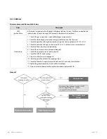
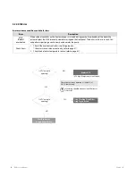
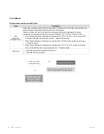
Scenario2
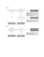
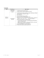
Scenario3
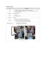
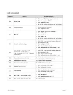
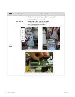
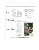
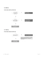
Is the flame detection
device normally
operating?
Is the flame current
detected?
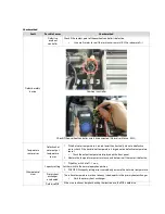
Clean or replace the flame rod
Check whether ground circuit is
properly installed.
Restart unit
Check the current #1 of CN 2: DC 1 - 20μA
(see page 56 for Wiring Diagram)
Check connector
(#1 of CN2)
NO
Yes
NO
Yes
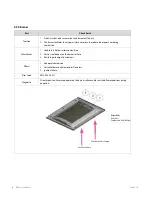
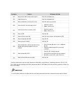
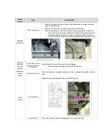
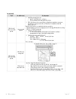
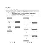
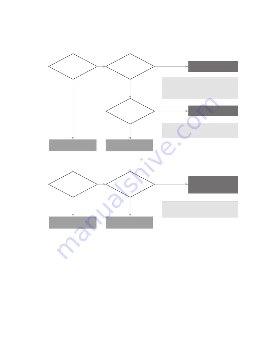
Is gas valve operating
normally?
Is gas valve open?
NO
Yes
Check connector
Check that gas valve is
open or check LP supply
Power OFF the unit
Check the voltage between #1 and #2 of CN 16:
22-24 VDC
Check the voltage between #1 and #3 of CON 4:
22-24 VDC
(see page 56 for Wiring Diagram)
Does the main
gas valve have proper
voltage?
NO
NO
Yes
Yes
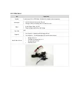
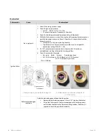
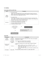
In case of LP gas model, low gas pressure can
cause “Ignition Failure”.
* Normal gas pressure: 8.0 - 13.5" w. c.
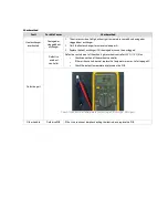
Check the flame rod
Summary of Contents for NCB-180
Page 3: ......
Page 16: ......
Page 135: ...132 NCB Service Manual Version 1 0 7 2 Burner Assembly...
Page 139: ...136 NCB Service Manual Version 1 0 7 4 Fan Gas Assembly...
Page 142: ...Memo...
Page 143: ...140 NCB Service Manual Version 1 0 Memo...
Page 144: ...Memo...
Page 145: ...142 NCB Service Manual Version 1 0 Memo...
Page 146: ...Memo...
Page 147: ...144 NCB Service Manual Version 1 0 Memo...
Page 148: ...Memo...


