background image

4   NCB Service Manual 

Version 1.0


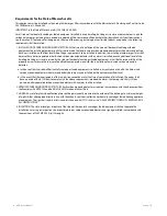
Requirements for the State of Massachusetts 

This appliance must be installed by a licensed plumber or gas fitter in accordance with the Massachusetts Plumbing and Fuel Gas Code 

248 CMR Sections 2.00 and 5.00. 
IMPORTANT: In the State of Massachusetts (248 CMR 4.00 & 5.00) 
For all side wall horizontally vented gas fueled equipment installed in every dwelling, building or structure used in whole or in part for 

residential purposes, including those owned or operated by the Commonwealth and where the side wall exhaust vent termination is 

less than seven (7) feet above finished grade in the area of the venting, including but not limited to decks and porches, the following 

requirements shall be satisfied: 

1. INSTALLATION OF CARBON MONOXIDE DETECTORS. At the time of installation of the side wall horizontal vented gas fueled 

equipment, the installing plumber or gasfitter shall observe that a hard wired carbon monoxide detector with an alarm and battery 

back‐up is installed on the floor level where the gas equipment is to be installed. In addition, the installing plumber or gasfitter shall 

observe that a battery operated or hard wired carbon monoxide detector with an alarm is installed on each additional level of the 

dwelling, building or structure served by the side wall horizontal vented gas fueled equipment. It shall be the responsibility of the 

property owner to secure the services of qualified licensed professionals for the installation of hard wired carbon monoxide 

detectors 

a. In the event that the side wall horizontally vented gas fueled equipment is installed in a crawl space or an attic, the hard wired 

carbon monoxide detector with alarm and battery back‐up may be installed on the next adjacent floor level. 

b. In the event that the requirements of this subdivision cannot be met at the time of completion of installation, the owner shall 

have a period of thirty (30) days to comply with the above requirements; provided, however, that during said thirty (30) day 

period, a battery operated carbon monoxide detector with an alarm shall be installed. 

2. APPROVED CARBON MONOXIDE DETECTORS. Each carbon monoxide detector as required in accordance with the above provisions 

shall comply with NFPA 720 and be ANSI/UL 2034 listed and IAS certified. 

3. SIGNAGE. A metal or plastic identification plate shall be permanently mounted to the exterior of the building at a minimum height 

of eight (8) feet above grade directly in line with the exhaust vent terminal for the horizontally vented gas fueled heating appliance 

or equipment. The sign shall read, in print size no less than one‐half (1/2) inch in size, “GAS VENT DIRECTLY BELOW. KEEP CLEAR OF 

ALL OBSTRUCTIONS”. 

4. INSPECTION. The state or local gas inspector of the side wall horizontally vented gas fueled equipment shall not approve the 

installation unless, upon inspection, the inspector observes carbon monoxide detectors and signage installed in accordance with 

the provisions of 248 CMR 5.08(2)(a)1 through 4. 


Summary of Contents for NCB-180

Page 1: ...chnician or professional who installed your boiler Contact a licensed professional for the affected system for example a plumber or electrician When you contact Technical Support please have the follo...

Page 2: ...e WHAT TO DO IF YOU SMELL GAS Donot trytolight any appliance Donot touch any electrical switch donot use any phone inyour building Immediately call your gas supplier from a neighbor s phone Follow the...

Page 3: ......

Page 4: ...Revisions Version Description of changes Date 1 00 First Issue October 27 2013 1 00 Reviewed BY...

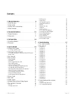
Page 5: ...y 55 4 6 Error Codes 55 4 7 Ladder Diagram 56 4 8 Electrical Diagnostic Point Wiring Diagram 57 4 9 Key Components Description 60 4 9 1 PCB 60 4 9 2 High Limit Switch 61 4 9 3 Thermistor 62 4 9 4 Fan...

Page 6: ...2 9 Flow Sensor 127 6 2 10 Circulation Pump 127 6 2 11 3 way Valve 128 6 2 12 Water Pressure Sensor 129 6 2 13 Space Heating Strainer 129 6 2 14 Auto Feeder Valve 130 6 2 15 DHW Heat exchanger 130 7 C...

Page 7: ...er to secure the services of qualified licensed professionals for the installation of hard wired carbon monoxide detectors a In the event that the side wall horizontally vented gas fueled equipment is...

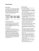
Page 8: ...dures installed by a non licensed installer and installation in violation of applicable rules laws or building codes Product purchased through the internet other e commerce channels or any installer t...

Page 9: ...H THE EXCEPTION OF THIS LIMITED WARRANTY NAVIEN DISCLAIMS ANY OBLIGATION OR LIABILITY WITH RESPECT TO THE PRODUCTS OR THEIR SALE AND USE AND NAVIEN NEITHER ASSUMES NOR AUTHORIZES THE ASSUMPTION OF ANY...

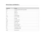
Page 10: ...atural Gas LP Propane Gas AP Air Pressure APS Air Pressure Sensor DHW Domestic Hot Water FM Fan Motor GARC Gas Air Ratio Control GPM Gallons Per Minute MGV Main Gas Valve RPM Revolutions Per Minute PC...

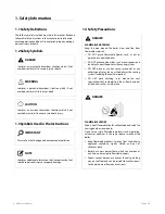
Page 11: ...ea around the boiler clear and free from flammable materials DO NOT place flammable liquids such as oils or gasoline etc near the boiler DO NOT place combustibles such as newspapers and laundry etc ne...

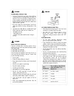
Page 12: ...meter Immediately call your gas supplier from the outside of the building Follow the gas supplier s instructions If you cannot reach your gas supplier call the fire department Notify your plumbing he...

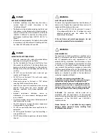
Page 13: ...omething is wrong with the unit DO NOT allow children to operate or otherwise handle the unit WARNING GAS TYPE and AC VOLTAGE This boiler is configured for Natural Gas from the factory If conversion t...

Page 14: ...nal components of the boiler with wet hands Doing so may result in electric shock CAUTION Do not attempt to repair or replace any part of the boiler unless it is specifically recommended in this manua...

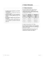
Page 15: ...a built in Circulation Pump and Air vent This appliance is fully modulating and provides central heating and domestic hot water Depending on the heat capacity each model is divided into three types 18...

Page 16: ......

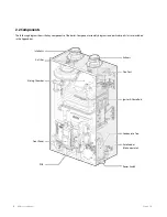
Page 17: ...shows the key components of the boiler Component assembly diagrams and particular parts lists are included in the Appendixes Intake Air Air Filter Mixing Chamber Front Panel PCB Exhaust Flue Duct Ign...

Page 18: ...ion Transformer Primary Heat Exchanger Secondary Heat Exchanger Pressure Sensor LWCO DHW Heat Exchanger Gas Valve DHW Inlet Filter with built in flow restrictor DHW Inlet DHW Outlet Flow Sensor APS Ai...

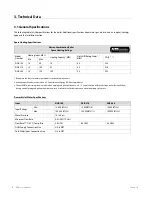
Page 19: ...fore selecting a boiler for installations having unusual piping and pickup requirements such as intermittent system operation extensive piping system etc Domestic Hot Water Specifications Navien Combi...

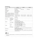
Page 20: ...in WC 0 1 in WC 0 66 in WC 0 03 in WC 0 98 in WC Gas Connection Size 3 4 in NPT Power Supply Main Supply 120V AC 60Hz Maximum Power Consumption 200W max 2A Materials Casing Cold rolled carbon steel H...

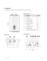
Page 21: ...Intake 2 in B Exhaust Gas Vent 2 in C Space Heating Supply 1 in D Space Heating Return 1 in E Hot Water Outlet DHW 3 4 in F Gas Supply Inlet 3 4 in G Cold Water Inlet DHW 3 4 in H Condensate Outlet 1...

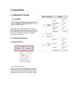
Page 22: ...t and the gas type 4 1 1 Setting the DIP Switches Circuit Board DIP Switches Set of DIP Switches 1 Set of 6 The DIP switches 1 on the circuit board configure the boiler s model and gas type settings T...

Page 23: ...h as temperature control modes Switch Function Setting 1 Temperature Control Return Water 1 ON Supply Water 1 OFF 2 Reserved 3 Reserved 4 Reserved 5 6 Country select USA Canada 5 OFF 6 OFF Reserved 5...

Page 24: ...ll system when an external pump is wired to the boiler Well Pump OFF 3 OFF 4 5 High Altitude 0 1 999 ft 0 609 m 4 OFF 5 OFF High Altitude Above 2 000 ft 610 m the boiler will de rate by 4 for each 1 0...

Page 25: ...vice Manual Version 1 0 Set of DIP Switches 2 Set of 2 The DIP SW 2 on the front panel configures the gas type setting SW1 NO Application Setting Remarks 1 Reserve 2 Gas type Natural Gas 2 OFF Propane...

Page 26: ...ssures equal to or less than 1 2 psi 3 5 kPa To measure the inlet gas pressure 1 Shut off the manual gas valve on the gas supply line 2 Open a hot water faucet The boiler should turn on and the gas in...

Page 27: ...mum Natural Gas Delivery Capacity in Cubic Feet ft3 per Hour 0 60 Specific Gravity 0 5 WC Pressure Drop Contact your gas supplier for BTU ft3 ratings Use 1 000 BTU ft3 for simplified calculations This...

Page 28: ...503 16 465 14 092 12 489 11 316 10 411 9 685 9 087 8 584 7 608 4 43 678 30 020 24 107 20 632 18 286 16 569 15 243 14 181 13 305 12 568 11 139 Maximum Liquefied Propane Delivery Capacity in Thousands...

Page 29: ...sories who is experienced in such work familiar with all precautions required and has complied with all of the requirements of the authority having jurisdiction In Canada The conversion shall be carri...

Page 30: ...is detached from the gas valve find location B the connection above the gas valve where it is attached to the fan motor assembly Carefully remove the four screws by hand using a Phillips screwdriver...

Page 31: ...r whenever they are disassembled The O ring must be in good condition and must be installed Failure to comply will cause a gas leak resulting in severe personal injury or death Figure 6 Orifice identi...

Page 32: ...set the DIP switches could cause carbon monoxide poisoning resulting in severe personal injury or death 17 Turn on the gas and water supply to the boiler 18 Measure and adjust the gas air ratio Optio...

Page 33: ...several hot water fixtures and set the boiler to operate at 2 stage MAX mode refer to page 19 and page 54 Measure the CO2 value at high fire If the CO2 values do not match Table 2 at high fire do not...

Page 34: ...rn clockwise to raise or counterclockwise to lower the offset value Figure 10 NOTE The set screw is located behind the screw on cover This must be removed first d At high fire do not check the offset...

Page 35: ...Displays the Supply Water Control mode status Return Water Control Displays the Return Water Control mode status Segment Displays the data set in each Segment according to display status Combustion Di...

Page 36: ...Remarks Diagnostic short key Display of information for service Mode short key Sets heating temperature hot water temperature Displays confirms of information for customers Converts in order of Setti...

Page 37: ...lay Possible only with power turned OFF Diagnostic Plus Reset Power long key 5Seconds Factory reset Possible only with power turned OFF All button LEDs will be turned on to their maximum when buttons...

Page 38: ...4 Normal Operation 1 Enter Normal Operating mode pressing the Power button for more than 300ms at Power Off mode 2 The Boiler will display the temperature and pressure of present supply water at 5 sec...

Page 39: ...ol Status Operating mode of Air Purge Function When the supply water pressure is 12 3 psi AIR and water pressure will repeat to display at 5 seconds intervals alternately 5 sec flashing 3 Level1 Error...

Page 40: ...nce while the error code is displayed the error will be released after RST displays for 3 seconds if the Boiler meets the conditions to release the error If releasing the error is not possible the err...

Page 41: ...djusting the water temperature read To prevent burns on page 9 carefully Water above 120 F 52 C can cause instant scalding severe burns or death To adjust the water temperature 1 Make sure that all ho...

Page 42: ...outgoing water temperature For Celsius mode ex at 60 For Fahrenheit mode ex 120 B Space heating return water temperature Display of the current space heating incoming water temperature For Celsius mod...

Page 43: ...15 Outdoor Temperature display for Fahrenheit mode with optional sensor ex at 59 G Outdoor reset curve Display of heat load 1 7 If Finned Tube Baseboard is set 1 Finned Tube Baseboard 2 FAN Coil 3 Cas...

Page 44: ...E displays CLR and deletes all the ERROR HISTORY DATA 5 Press the Reset button once to return to the Normal operation mode 6 If there is no button input for 5 minutes then it automatically returns to...

Page 45: ...on input for 1 hour then it automatically returns to the Normal operation mode Item Description Display A Space heating supply water temperature Display of the current space heating outgoing water tem...

Page 46: ...ex at 15 Outdoor Temperature display for Fahrenheit mode with optional sensor ex at 59 G Outdoor reset curve Display of heat load 1 7 If Finned Tube Baseboard is set 1 Finned Tube Baseboard 2 FAN Coi...

Page 47: ...git ex 3600rpm M Current RPM Current fan motor RPM display Display of RPM by omitting the last digit ex 3600 rpm N Target APS Target APS voltage value display Display of the APS value as voltage up to...

Page 48: ...4th digit represents the type of market ex Capacity 180 condensing for the American market ex Capacity level 240 for the Korean market ex Setting error R Information on Gas Type Display of current ga...

Page 49: ...Mode Used to test the operation condition of the boiler 3 Press the MODE Button once enters boiler to the currently displayed mode 4 Press the RESET button once returns the boiler to the Normal Opera...

Page 50: ...in use B Outdoor Reset Heat Road Setting This mode is used to configure the heat load type to be used with the Outdoor Reset Control mode A preset or user defined temperature range is selected automa...

Page 51: ...ature Set point 9 5 104 40 70 21 For Celsius mode ex at 21 For Fahrenheit mode ex at 70 Highest Outdoor Reset is not used E Boost Interval Time Setting The boost interval time may be set to prevent in...

Page 52: ...overrun time is the duration that the circulation pump will continue to run when the space heating supply or return temperatures reach the set values for boiler operation stop temperatures and the bur...

Page 53: ...changes based on the supply absolute MAX temperature range Setting range Default MIN Set point 36 20 194 90 180 82 For Celsius mode ex at 82 feed water control For Fahrenheit mode ex at 180 O Supply A...

Page 54: ...eating or DHW demand Setting range Default 12 30 PSI 12 PSI If water pressure is 18 psi S All Parameters Initialization This menu may be used to initialize all the parameters set with the boiler To in...

Page 55: ...e and Dual Venturi Test 6 During the component check operation a test is automatically performed without pressing additional buttons except the 3 Way Valve and Dual Venturi Test 7 The 3 Way Valve and...

Page 56: ...Way Valve 3 Way Valve will be turned On upon entering Test mode and pressing the button each time converts the state from On Off or Off On Whenever the button is pressed the condition is toggled as On...

Page 57: ...pressed once then it returns to the Special Parameter mode Displayed as the previously entered item 3 OPR 4 If there is no button input for 3 hours then it automatically returns to the Normal Operati...

Page 58: ...ption Display FACTORY RESET Displays for 5 seconds 4 5 Version Display Press the Diagnostic button for more than 10 seconds at Power Off mode will display the Main Controller firmware version for 3 se...

Page 59: ...pplement Flame Rod Flow Sensor APS Fan Hall Sensor DHW Inlet Thermistor 1 DHW Outlet Thermistor 2 Heating Supply Thermistor 1 Heating Return Themistor Exhaust Thermistor Outdoor Thermistor WPS Flow Se...

Page 60: ...ernal AC Output Front Panel Air Pressure Sensor Water Pressure Sensor DHW Flow Sensor Optional Outdoor Thermostat High Limit S W Inlet1 Thermistor Inlet2 Thermistor Outlet2 Thermistor Outlet1 Thermist...

Page 61: ...e B Outdoor sensor CN11 DC 0 5V Voltage changes according to temperature C Flow Sensor CN5 1 3 RED BLACK DC 12V Confirm steady voltage CN5 2 3 WHITE BLACK PULSE Check Pulse D Water Pressure Sensor CN2...

Page 62: ...en the unit is igniting L Pump CN18 1 3 YELLOW WHITE ON AC 96 138V OFF 0V Confirm voltage as operating M Fan Motor CN8 4 7 BLACK RED DC 127 184V Confirm steady voltage CN8 2 4 BLACK YELLOW DC 15V Conf...

Page 63: ...he unit Failure Event Malfunctioning PCB Effects A component may not operate within the unit and could produce an error code In most cases of PCB failure the whole unit will not operate until the prob...

Page 64: ...92 C in heat exchanger will activate the high limit switch Failure Event Unable to detect excessively high water temperature if switch fails Effects Unable to shut down the boiler if the water temper...

Page 65: ...205 E218 E407 E421 Diagnostic 1 Visual inspection Connection and or breakage of wires 2 Check the resistance of the sensor Stop operating and lower the temperature before checking Color Number of wire...

Page 66: ...rew is loose and or the fan is disassembled 3 Disconnected or defective fan connection terminal assembly Effects 1 Unstable combustion condition 2 Unit vibrating and noise 3 The boiler is not operatin...

Page 67: ...ite during the ignition process 2 Produces multiple unsuccessful attempts to ignite Effects 1 The unit cannot ignite during the ignition process and E003 or E004 error codes will display 2 Durability...

Page 68: ...nsuccessful attempts to ignite Effects 1 The unit cannot ignite during the ignition process and E003 or E004 error codes will display 2 Durability of the igniter wears down Error Code E003 E004 Diagno...

Page 69: ...e Effects 1 The boiler is not operating 2 Produces excessive carbon monoxide emissions Error Code E110 Diagnostic 1 Visual inspection Connection and or breakage of wires 2 Voltage check Check range of...

Page 70: ...e situations Failure Event Unable to open close Effects 1 No flames 2 No operation of the unit Error Code E003 E012 Diagnostic 1 Visual inspection Connection and or breakage of wires 2 Check if the so...

Page 71: ...1 Unable to initialize sustain combustion 2 Dust or soot deposit on the burner surface 3 Possible gas leakage from burners Effects 1 Abnormal combustion 2 Unstable flame conditions and or flame loss 3...

Page 72: ...or water leakage from the water flow sensor Effects 1 Ignition sequence does not start 2 Stop operating once detecting water leakage Error Code E439 Diagnostic 1 Visual inspection Connection and or br...

Page 73: ...mizes the heat loss Failure Event 1 Water and or exhaust gas leakage through a crack 2 Improper heat transfer can cause the water in the heat exchanger to boil due to possible scale formation Effects...

Page 74: ...ich minimizes heat loss Failure Event 1 Water and or exhaust gas leakage through a crack 2 Improper heat transfer can cause the water in heat exchanger to boil Effects 1 Exhaust gas leakage 2 Excessiv...

Page 75: ...kage through a crack 2 Improper heat transfer can cause the cold water in heat exchanger Effects Temperature fluctuations in the hot water outlet and or leaking Error Code E016 E030 E353 Diagnostic Th...

Page 76: ...r measure water flow rate when the pump is called to operate Effects 1 The boiler freezes 2 Temperature fluctuations when the boiler is set to internal recirculation 3 Hot water is not quickly availab...

Page 77: ...mestic hot water in DHW mode Effects In the case that the temperature of space heating is lower than the set temperature it blocks the water flow path for domestic hot water so that heating water can...

Page 78: ...Effects Water filling system does not operate automatically Error Code E351 E352 E353 Diagnostic 1 Visual inspection check the circulation pump connection wire 2 Voltage check Check range of voltage s...

Page 79: ...re Event 1 Water filling system does not operate automatically 2 Water filling system operates continuously Effects 1 System is low water pressure 2 If system is high water pressure for automatic fill...

Page 80: ...SET Abnormal APS open short initial value or no answer No error display CH System E205 2 Abnormal H E outlet thermistor open or short Auto RESET E218 1 Abnormal H E inlet thermistor open or short Alar...

Page 81: ...eck the heat exchanger a flush may be necessary E030 Exhaust Overheat exhaust limit switch shuts down the unit when the flue temperature exceeds 230 F 110 C for more than 10 minutes 1 Turn OFF the sys...

Page 82: ...al operation outdoor temperature sensor appears only when the outdoor reset curve is enabled 1 Ensure that the outdoor reset curve is configured properly 2 Check the outdoor temperature sensor wiring...

Page 83: ...e flame rod wiring and grounding 6 Check if the air pressure hose is broken or clogged 7 Check if the air pressure sensor works properly 8 Check the PCB DIP switch settings 9 Adjust the offset pressur...

Page 84: ...1 of CN2 NO Yes NO Yes Is gas valve operating normally Is gas valve open NO Yes Check connector Check that gas valve is open or check LP supply Power OFF the unit Check the voltage between 1 and 2 of...

Page 85: ...nd stage MAX combustion setting DIP S W 1 1 ON 5 If a CSST connector has been used check to ensure that it is not been overtightened resulting in the seal obstructing gas flow 6 Check the meter class...

Page 86: ...from the metallic part of the burner Ensure that the insulating gasket is installed between the electrode and burner casing Check the input power to the ignition transformer AC 96 138 V If there is s...

Page 87: ...multi meter if the input power is DC 22 24 V 2 Replace the PCB if power is not supplied 3 If power supply is normal check if the coil is open Check the resistance refer to page 125 4 Check if the sole...

Page 88: ...t with the case Or use a multi meter to measure the flame sensing current normally 3 4 A Measuring flame current Grounding wire position Flame loss and noise occurs at ignition Check if there are any...

Page 89: ...e range 4 Check the PCB and replace if defective Check method Failure mode Cause Check method Flame before after combustion Leakage from main gas valve Replace the gas flame if flame occurs before com...

Page 90: ...nel Check items 1 Measure with a manometer the gas supply pressure NG 3 5 10 5 W C LP 8 13 5 W C 2 Check the Gas meter Capacity 3 Tighten the ground connection screws on heat exchanger 4 Check if the...

Page 91: ...tor If a CSST connector has been used check to ensure that it is not been overtightened resulting in the seal obstructing gas flow 4 Check the gas meter capacity Example Gas meter Boiler Furnace Domes...

Page 92: ...necessary Other trouble PCB DIP switch setting error Check the PCB DIP switch settings Refer to page 19 Defective PCB If the issue continues despite checking above items replace the PCB Check the fla...

Page 93: ...rforms post purge continuously and operates the pump Check items 1 Check if the overheat controller is working properly Check resistance value or continuity refer to page 61 2 Check the hot water temp...

Page 94: ...sensor check if the deviation of temperature is large due to a defective temperature sensor Check the output temperature displayed on the front panel 2 Measure the temperature sensor resistance and d...

Page 95: ...ure of 230 F 110 C for 10 minutes or over E030 error code will display and perform post purge Automatically cleared 2 When the controller detects the exceeding temperature of 140 F 60 C while performi...

Page 96: ...s damaged or cannot be unclogged Defective part Defective overheat controller Defective contact point of the exhaust gas overheat controller 230 F 110 C Max Check connection of the overheat controller...

Page 97: ...rating normally Check connector 9 and 10 of CN13 NO Resistance between 9 and 10 of CN13 is from 2k to 300k at normal condition see page 56 for Wiring Diagram Is heat exchanger thermistor normally oper...

Page 98: ...al Venturi is operating correctly 2 Check that the wiring harness is connected correctly and the cables are not damaged Yes Reset the Unit Is Dual venturi closed NO Is Dual venturi repeatedly open and...

Page 99: ...3 Wait until Fan Auto Adjusting is complete 4 Enter the Dual Venturi Test Mode and perform a test 1 Repeat the test at least twice Turning the unit ON and OFF once makes one test cycle ON OFF ON OFF i...

Page 100: ...al Check items 1 Check if the fan motor works normally using the component test mode refer to page 21 2 Check the power supply to the fan Black Red approx DC 127 184 V 3 If RPM is significantly low wh...

Page 101: ...operating and the power supply is normal Follow the instructions listed below and replace the fan 1 Unplug the power cable to the unit and then wait for 10 seconds until the remaining SMPS voltage com...

Page 102: ...ndard value Check items 1 Check if the venturi burner hole is clogged 2 Check if the condensation drain line or the drain is clogged 3 Check the flue and exhaust to verify proper installation and clea...

Page 103: ...obstructions 2 Check if rainwater is collected due to vertical installation of the air intake pipe Exhaust gas flows in through the supply pipe If the exhaust gas enters into the air supply pipe abnor...

Page 104: ...resistance of the temperature sensor Defective if it is 30k or higher Replace the temperature sensor if the resistance value is abnormal Check the temperature displayed on the front panel Possible Is...

Page 105: ...boiler initiates shutdown Check items 1 Check if the heat exchanger input temperature sensor connector is wet due to any reason including leakage 2 Replace the defected heat exchanger input temperatu...

Page 106: ...the temperature sensor Defective if it is 30k or higher Replace the temperature sensor if the resistance value is abnormal refer to page 62 Check the temperature displayed on the front panel refer to...

Page 107: ...not refilled Check if the cold water valve is closed or frozen Check if the auto feeder valve works normally 2 Water overflows through condensed water hose Check the left drain valve of the main heat...

Page 108: ...Replace the auto feeder valve if power is supplied normally 3 Replace the PCB if power is not supplied Check if the filter is clogged with debris Water flow over through the condensed water hose Drain...

Page 109: ...ng leakage 2 Check the Auto Feeder Sensor 3 Check the controller Check method Fault Possible Causes Check method E352 High water pressure Check the pressure increase conditions high water pressure of...

Page 110: ...ater pipe input water pressure sensor is wet due to any reason including leakage 2 Replace the water pressure sensor 3 Check the controller Check method Fault Possible Causes Check method Anormal wate...

Page 111: ...nt panel Check items 1 Check if the hot water temperature sensor connector is wet due to any reason and if the connector is connected properly 2 Check if the temperature sensor is open or short Is the...

Page 112: ...k the temperature displayed on the front panel refer to page 39 Possible Issues Defective PCB If the issues continue despite checking the items above replace the PCB DHW outlet elbow input temperature...

Page 113: ...he front panel Check items 1 Check if the cold water temperature sensor connector is wet due to any reason and if the connector is connected properly 2 Check if the temperature sensor is open or short...

Page 114: ...the temperature sensor Defective if it is 30k or higher Replace the temperature sensor if the resistance value is abnormal refer to page 62 Check the temperature displayed on the front panel refer to...

Page 115: ...ctive flow sensor The system displays 439E cleared manually on the front panel and switches the unit operation into the Lock Out mode gas valve and ignition transformer locked Check items 1 Check the...

Page 116: ...lied 4 Replace the flow sensor if no flow is detected while the operating voltage is normal Other trouble Defective PCB If the issue continues despite the checking of items above the PCB is defective...

Page 117: ...ith the PCB internal circuit Power supply error Check with a multi meter if the PCB is supplied with the proper voltage Check with a multi meter if the voltage at the electrical outlet is AC 102 132 V...

Page 118: ...ation by PCB 1 Click the Reset button on Front panel 2 Turn the POWER to the unit OFF then ON Disconnect then reconnect power if necessary 3 If the system still displays E594 replace the main PCB 5 2...

Page 119: ...displays the error message E740 on the front panel If this occurs the boiler changes the control mode from Reset Curve Mode to Normal Mode Check items 1 Check the parameter setting refer to page 46 2...

Page 120: ...t panel properly connected to the PCB Reconnect panel to the PCB 1 step Reset the unit 2 step If problem persists replace the PCB and Front NO Yes Yes Yes Is the LWCO installed properly Check the fact...

Page 121: ...e 54 If noise occurs at standard value adjust setting above below the standard 2 Gas supply error due to defective air pressure sensor 3 If the same error is repeated it is due to a defective PCB Nois...

Page 122: ...er temperature sensor may not work be working properly Low hot water temperature Hot water setting error Check the hot water temperature setting on the front panel Water mixed with cold water The temp...

Page 123: ...valve Check if the wire is fixed and properly attached on the main side of the heat exchanger Normal assembly Short circuit due to defective assembly Wiring near the heat exchanger Circuit breaker op...

Page 124: ...with soap bubble solution Bubbles indicate a gas leak that must be corrected 7 Check the performance and operation after the boiler has been serviced To remove and replace any parts from the boiler yo...

Page 125: ...in Figure 3 below Open the housing to expose the fuse Figure 3 4 Replace the old fuse with the new part 5 Ensure that the new fuse is of an equivalent rating and that it is properly fixed inside the h...

Page 126: ...screws for the fan motor replacement with high torque drill This may cause damage to the part s 6 2 4 Flame Rod 1 Turn off the gas supply to the unit 2 Disconnect the unit from the power supply 3 Tur...

Page 127: ...ull out the Ignition Transformer 8 Replace the old Ignition Transformer with the new part and then use the 2 screws to secure the part 9 Reconnect the Ignition Transformer insulated cables to the flam...

Page 128: ...water supply power supply and gas supply to the unit NOTE Confirm that the new air pressure sensor is in the proper position before turning the unit back on 6 2 7 Main Gas Valve 1 Turn off the gas su...

Page 129: ...kets with new parts to ensure tight seals between connections Ensure that all properly sized O rings are used for the replacement 6 2 8 Condensate Trap 1 Turn off the gas supply to the unit 2 Disconne...

Page 130: ...nstall the flow sensor into heat exchange and reattach the stainless clip Ensure that the flow sensor is properly connected to the heat exchanger and that the clip is tightly holding the two parts tog...

Page 131: ...Reconnect the wiring connector at the pump 13 Install the Main PCB back onto the unit by using the four screws 14 Turn on water supply power supply and gas supply to the unit 15 Open a hot water tap...

Page 132: ...th new water pressure sensor 7 Connect the water pressure senor wire housing NOTE Always use proper O rings at the water pressure valve connection to ensure tight seals 6 2 13 Space Heating Strainer F...

Page 133: ...r and remove the stainless nut from the Auto feeder valve Figure 30 6 Replace with Auto feeder valve 6 2 15 DHW Heat exchanger 1 Turn off the gas supply to the unit 2 Turn off the 120V power supply to...

Page 134: ...e Assembly Description Part Remark 1 Intake Air Duct Assembly 30008662B 2 Exhaust Pipe Assembly 30008673A 3 Case 20027375A 4 Intake Air Filter 20007668A 5 Air Pressure Sensor 30010346A 6 PCB 30012262A...

Page 135: ...132 NCB Service Manual Version 1 0 7 2 Burner Assembly...

Page 136: ...hanger Ass y 30012322A NCB 180 30012321A NCB 210 30012317A NCB 240 9 Thermistor Exhaust 30009478A 10 Thermistor Water 30008366A 11 High Limit Switch 30002558A 12 Fastener 20007859A 13 O Ring P19 20017...

Page 137: ...1 0 7 3 Waterway Assembly Description Part Remark 1 DHW Heat Exchanger 30008181A NCB 180 30005017A NCB 210 240 2 Thermistor 30008366A 3 O Ring P18 20006954A 4 DHW Outlet Elbow 30012328A 5 Packing 200...

Page 138: ...0 3 Way Outlet Adaptor A 30012331A 21 Packing 20011380A 22 Connection Adaptor 20011408A 23 3 Way Valve 30004816C 24 Fastener 20007733A 25 Water Fill Pipe 30012247A 26 Space Heating Supply Adaptor A 20...

Page 139: ...136 NCB Service Manual Version 1 0 7 4 Fan Gas Assembly...

Page 140: ...23861A NCB 180 20019141A NCB 210 240 7 Venturi Packing 20022660A NCB 180 8 Gas Orifice 20024159A NCB 180 NG 20024190A NCB 210 240 NG 20019144A NCB 180 LP 20024189A NCB 210 240 LP 9 O Ring P34 20019090...

Page 141: ...ng the Inlet Water Filter YES NO Cleaning the Return Filter YES NO Checking the Intake Air Filter YES NO Flushing the Heat Exchanger YES NO Replacement of Parts 8 3 Maintenance Schedules Owner maintan...

Page 142: ...Memo...

Page 143: ...140 NCB Service Manual Version 1 0 Memo...

Page 144: ...Memo...

Page 145: ...142 NCB Service Manual Version 1 0 Memo...

Page 146: ...Memo...

Page 147: ...144 NCB Service Manual Version 1 0 Memo...

Page 148: ...Memo...

Page 149: ...146 NCB Service Manual Version 1 0 Memo...

Reviews: