


26 NCB Service Manual
Version 1.0
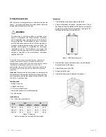
4.3 Gas Conversion
NCB Series boilers are configured for use withNatural Gas from the
factory. If conversion to Propane Gas is required, the conversion
kit supplied with the boiler must be used.
WARNING
This conversion kit shall be installed by a qualified service
agency* in accordance with Navien America’s instructions
and all applicable codes and requirements of the authority
having jurisdiction. The information in these instructions
must be followed to minimize the risk of fire or explosion or
to prevent property damage, personal injury or death. The
qualified service agency is responsible for the proper
installation of this kit. The installation is not proper and
complete until the operation of the converted appliance is
checked as specified in the manufacturer’s instructions
supplied with the kit.
* A qualified service agency is any individual, firm, corporation or
company which either in person or through a representative is
engaged in and is responsible for the connection, utilization, repair or
servicing of gas utilization equipment or accessories; who is
experienced in such work, familiar with all precautions required, and
has complied with all of the requirements of the authority having
jurisdiction.
In Canada
: The conversion shall be carried out in accordance with
the requirements of the provincial authorities having jurisdiction
and in accordance with the requirements of the CAN-B149.1 and
CAN1-B149.2 Installation Code.
Tools Required:
Phillips Screwdriver
Flathead Screwdriver
5/32” or 4mm Allen Wrench
Combustion Analyzer or Dual Port Manometer
Gas Leak Detector
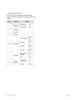
Included Items:
Gas Orifice (refer to table below)
Boiler
NG
NP
1STAGE
2STAGE
1STAGE
2STAGE
NCB-180
Ø4.80
Ø5.95
Ø3.80
Ø4.70
NCB-210
Ø6.10
Ø6.30
Ø4.50
Ø4.80
NCB-240
Ø6.10
Ø6.30
Ø4.50
Ø4.80
Table 1. Orifice size
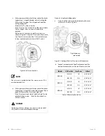
Gas Pressure and Conversion Kit Number Labels
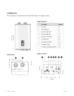
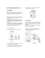
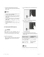
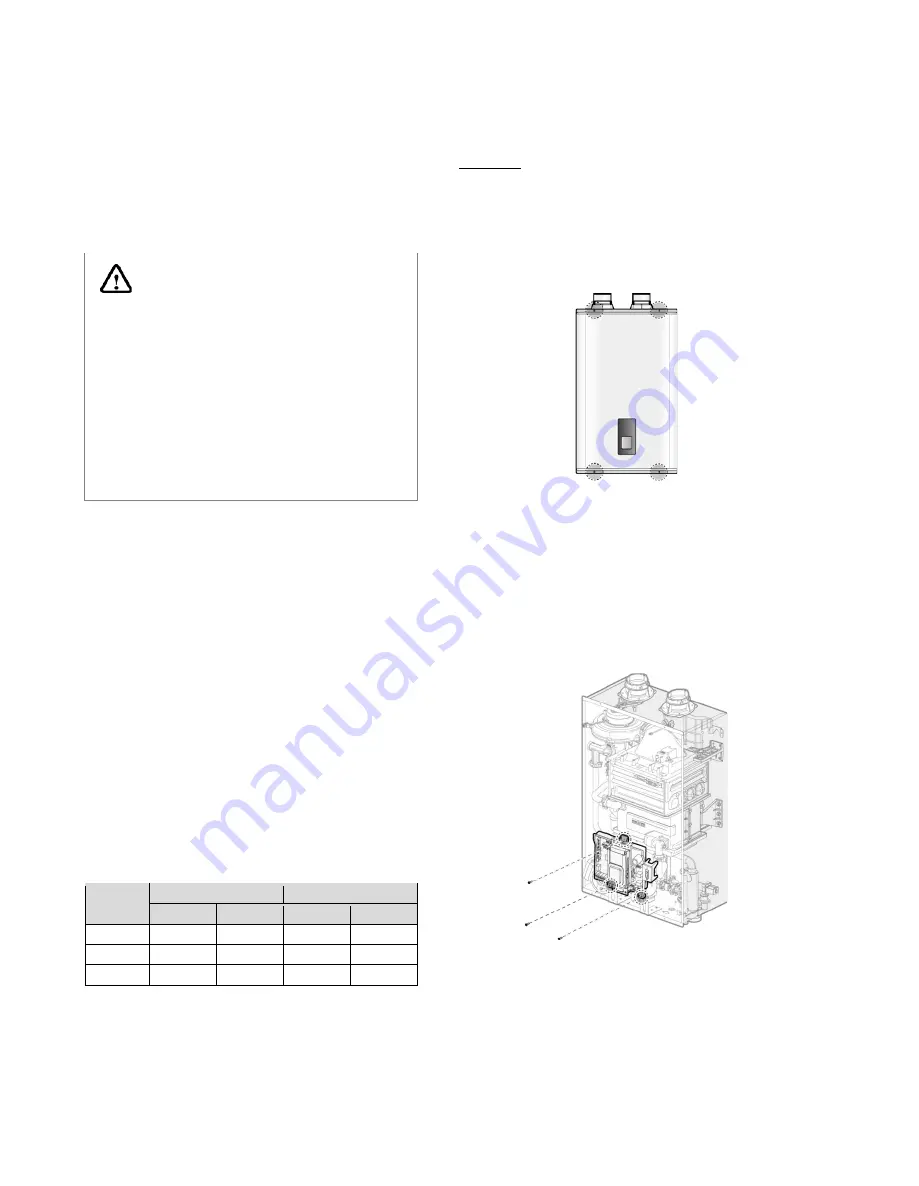
Procedure:
1.
Turn off both gas and water supply to the boiler.
2.
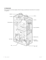
Using a Phillips hand screwdriver, remove 4 screws (2 from
the top and 2 from the bottom) of the front cover assembly
to gain access to the internal components. See Figure 1 for
illustration of the front cover on the unit.
Figure 1. NCB Series Front cover
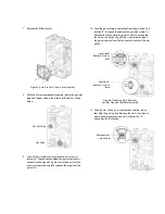
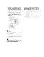
3.
Once the front cover is removed, place it in a safe location
to prevent accidental damage.
4.
Label all the wires on the PCB.
5.
Disconnect all the wires.
6.
Loosen the three screws indicated in the figure 3
Summary of Contents for NCB-180
Page 3: ......
Page 16: ......
Page 135: ...132 NCB Service Manual Version 1 0 7 2 Burner Assembly...
Page 139: ...136 NCB Service Manual Version 1 0 7 4 Fan Gas Assembly...
Page 142: ...Memo...
Page 143: ...140 NCB Service Manual Version 1 0 Memo...
Page 144: ...Memo...
Page 145: ...142 NCB Service Manual Version 1 0 Memo...
Page 146: ...Memo...
Page 147: ...144 NCB Service Manual Version 1 0 Memo...
Page 148: ...Memo...


