126 NCB Service Manual
Version 1.0
7.
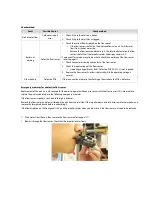
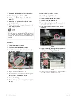
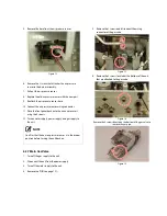
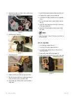
Remove the 4 screws directly from the bottom of the gas
valve to remove the elbow.
Figure 16
8.
Replace the O-ring where the gas valve assembly
attaches to the elbow. Make sure the old O-ring is
discarded.
9.
Replace the old gas valve with the new part and reattach
the elbow and gas pipe to the gas valve.
10.
Reconnect the gas valve assembly to the unit by using
the 4 screws at the elbow and 2 screws at the gas pipe.
11.
Reattach the gas valve wiring connector.
WARNING
Failure to correctly assemble the components according
to these instructions may result in a gas leak or
explosion.
12.
Check that all gas connections are tightly sealed to
ensure that no gas leaks are present.
13.
Turn on water supply, power supply, and gas supply to
the unit.
14.
Verify the gas pressures to the unit with the values
provided in this Service Manual.
NOTE
Always replace the old O-rings and gaskets with new
parts to ensure tight seals between connections. Ensure
that all properly sized O-rings are used for the
replacement.
6.2.8 Condensate Trap
1.
Turn off the gas supply to the unit.
2.
Disconnect the unit from the power supply.
3.
Turn off the water supply to the unit.
4.
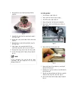
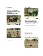
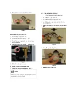
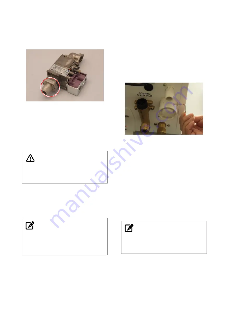
Remove the pin that secures the condensate drain cap
and then remove the cap. Use a bucket to collect the
condensate.
Figure 17
5.
Detach the condensate piping from the unit.
6.
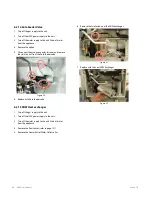
Remove the 2 screws located at the bottom of the unit
that are attached to the condensate trap.
7.
Loosen the clip that secures the hose to the condensate
trap, and then pull off the hose.
8.
Remove the old condensation trap and replace it with
the new part.
9.
Reconnect the hose to the condensate trap.
10.
Reattach the condensation trap to the unit and secure it
using the 5 screws.
11.
Replace the controller to its original position.
12.
Turn on the water supply, power supply, and gas supply
to the unit.
NOTE
Ensure that the condensate drain trap is completely
inserted into the condensate fitting to eliminate leaking.
Use the pin to secure the cap to the fitting.
Summary of Contents for NCB-180
Page 3: ......
Page 16: ......
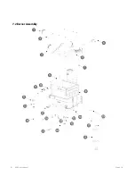
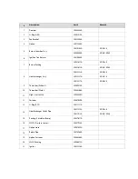
Page 135: ...132 NCB Service Manual Version 1 0 7 2 Burner Assembly...
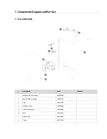
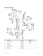
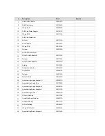
Page 139: ...136 NCB Service Manual Version 1 0 7 4 Fan Gas Assembly...
Page 142: ...Memo...
Page 143: ...140 NCB Service Manual Version 1 0 Memo...
Page 144: ...Memo...
Page 145: ...142 NCB Service Manual Version 1 0 Memo...
Page 146: ...Memo...
Page 147: ...144 NCB Service Manual Version 1 0 Memo...
Page 148: ...Memo...

