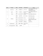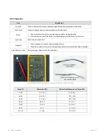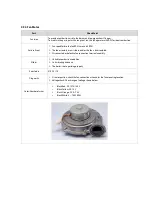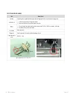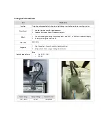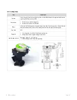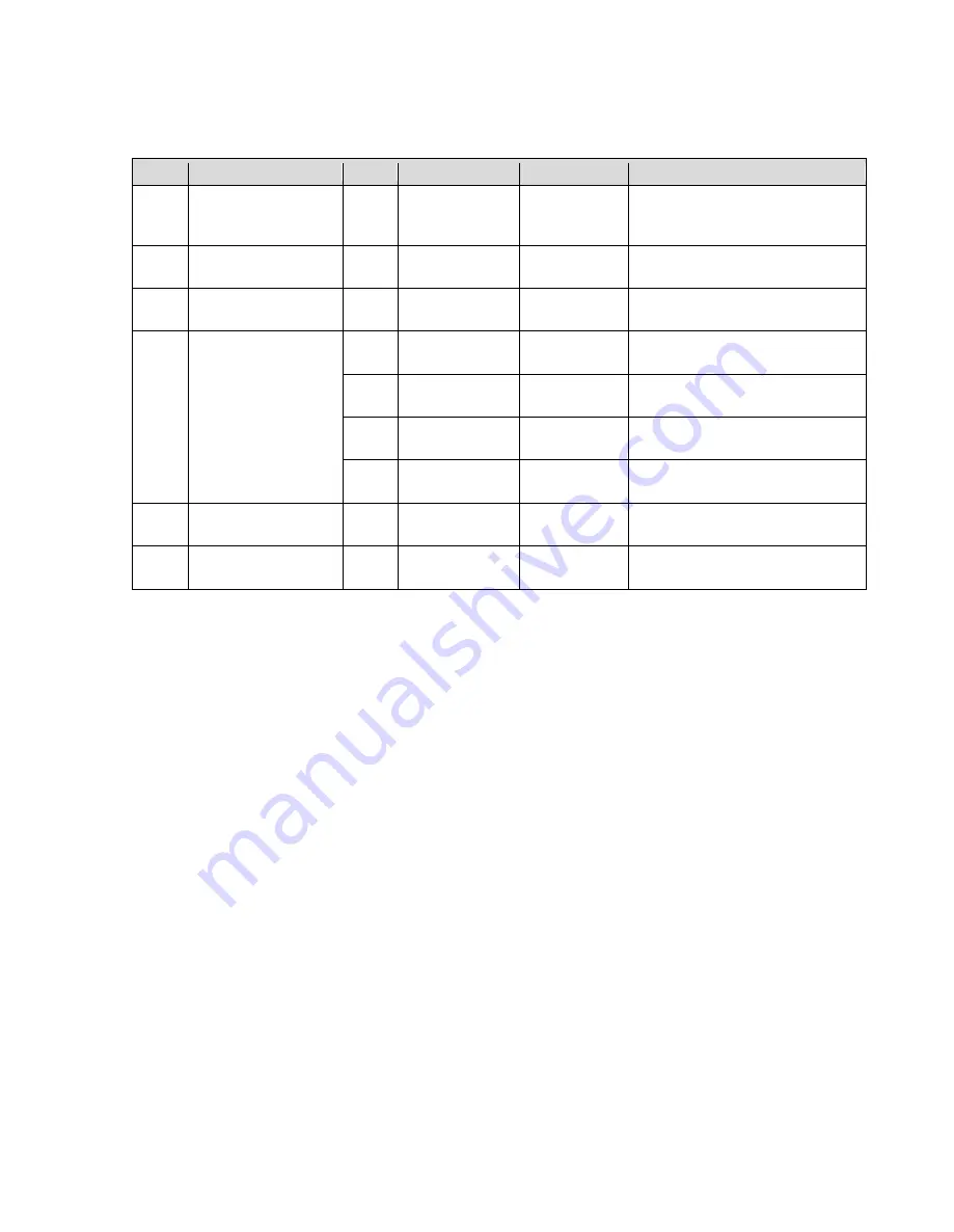
Point
Function
CN No.
Wire Color
Normal Value
Check
J
Power Input
CN1
1-2
WHITE-BLACK
AC 97~138V
Confirm appropriate power source.
Confirm the FUSE.
Confirm the circuit breaker.
K
Igniter
CN17
1-2
BLUE-BLUE
ON : AC 97~138V
OFF : 0V
Confirm voltage when the unit is
igniting.
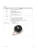
L
Pump
CN18
1-3
YELLOW-WHITE
ON : AC 96~138V
OFF : 0V
Confirm voltage as operating.
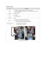
M
Fan Motor
CN8
4-7
BLACK-RED
DC 127~184V
Confirm steady voltage.
CN8
2-4
BLACK-YELLOW
DC 15V
Confirm steady voltage.
CN8
3-4
BLACK-ORANGE
DC 0~7.5V
Voltage changes relative to fan
operation.
CN8
1-4
BLACK-WHITE
0~6500rpm
Check PULSE.
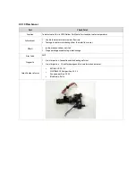
N
Auto Feeder Valve
CN21
1-2
PURPLE- PURPLE
ON: DC 22~24V
OFF: 0V
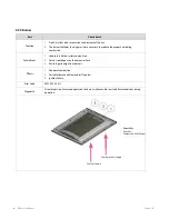
O
Front Panel Controller
CON1
1~14
All BLACK
Summary of Contents for NCB-180
Page 3: ......
Page 16: ......
Page 135: ...132 NCB Service Manual Version 1 0 7 2 Burner Assembly...
Page 139: ...136 NCB Service Manual Version 1 0 7 4 Fan Gas Assembly...
Page 142: ...Memo...
Page 143: ...140 NCB Service Manual Version 1 0 Memo...
Page 144: ...Memo...
Page 145: ...142 NCB Service Manual Version 1 0 Memo...
Page 146: ...Memo...
Page 147: ...144 NCB Service Manual Version 1 0 Memo...
Page 148: ...Memo...

