background image

Chapter 7

Advanced Application Topics

©

 National Instruments Corporation

7-23

BridgeVIEW User Manual

How Do You Limit User Access to HMI Objects?

You can use security information to control visibility attributes on HMI 
objects. There is a set of security VIs you can use to implement security in 
your HMI, found in the System»Security palette. For more information 
about these or any other VIs, refer to Appendix A, 

HMI Function 

Reference

As you develop your operator interface panels, you might want to restrict 
access to certain controls (inputs) or indicators (outputs). To do this, you 
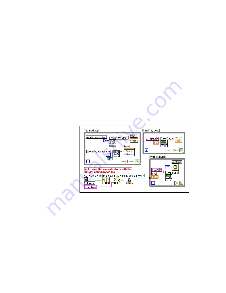
must add a security loop to your Operator Interface VI. Figure 7-6 shows 
how to use the Security Monitor VI to control the visible and disabled 
attributes of a front panel control and indicator. You can apply two types of 
security to a control: operability and visibility. By default, controls always 
operate and are visible. A security level of zero applies to the control, 
meaning that any user with access level zero or higher (all users) can 
operate the control.

Figure 7-6.  

Using the Security Monitor VI to Control Visibility

To limit user access in your HMI, pop up on the control terminal in the 
diagram for which you want to apply security and select Create»Attribute 
Node
. Resize the attribute node so both the “Visible” and “Disabled” 
attributes are available. Then wire the “Visible” attribute setting output to 
the “Visible” terminal and the “Disabled” attribute setting output to the 
“Disabled” terminal.

Also connect the shutdown output of the Security Monitor VI to a NOT 
function, and the output of the NOT function to the continuation node of 

Summary of Contents for BridgeVIEW

Page 1: ...User Manual BridgeVIEW User Manual May 1998 Edition Part Number 321294C 01...

Page 2: ...36 Canada Ontario 905 785 0085 Canada Qu bec 514 694 8521 Denmark 45 76 26 00 Finland 09 725 725 11 France 01 48 14 24 24 Germany 089 741 31 30 Hong Kong 2645 3186 Israel 03 6120092 Italy 02 413091 Ja...

Page 3: ...f action whether in contract or tort including negligence Any action against National Instruments must be brought within one year after the cause of action accrues National Instruments shall not be li...

Page 4: ...dgeVIEW Concepts Chapter 1 Introduction Welcome to BridgeVIEW 1 1 Required System Configuration 1 2 Installation 1 2 What Is BridgeVIEW 1 3 How Does BridgeVIEW Work 1 3 G Programming 1 4 Tag Configura...

Page 5: ...n 2 7 String 2 7 Tag 2 8 BridgeVIEW Environment Project Menu 2 10 What Is the BridgeVIEW Engine Manager 2 12 What Are System Errors and Events 2 15 What Is the Tag Browser 2 16 What Is the Tag Monitor...

Page 6: ...Options 3 16 Item Configuration 3 18 Item Configuration Options Configuring Item Names 3 18 Item Configuration Options Configuring Item Resources 3 18 What Is a Memory Tag 3 19 When Should You Use a M...

Page 7: ...e Shifts 3 44 How Do You Configure Engine Parameters 3 44 How Do You Launch Server Configuration Utilities from the Tag Configuration Editor 3 46 How Do You Access or Change Tag Configuration Informat...

Page 8: ...isplay Event History Information 5 6 How Do You Acknowledge Alarms 5 6 How Do You Configure Logging and Printing of Alarms and Events 5 10 How Do You Log Alarms and Events 5 12 How Do You Print Alarms...

Page 9: ...ou Configure Security with the Panel G Wizard 7 3 How Do You Configure When a Button Will Be Polled 7 3 VI Server Functions 7 5 How Do You Control Panel Size 7 6 How Do You Control Panel Visibility 7...

Page 10: ...rom a File 7 20 How Do You Import Users from Another Computer on the Network 7 21 How Do You Modify a User s BridgeVIEW Environment Privileges 7 22 Operator Interface Security 7 22 How Do You Limit Us...

Page 11: ...9 6 VI Documentation 9 9 What is a SubVI 9 12 Hierarchy Window 9 12 Search Hierarchy 9 14 Icon and Connector 9 14 Opening Operating and Changing SubVIs 9 19 How Do You Debug a VI 9 21 Chapter 10 Custo...

Page 12: ...ributes Chapter 14 Arrays Clusters and Graphs Arrays 14 1 How Do You Create and Initialize Arrays 14 1 Array Controls Constants and Indicators 14 2 Auto Indexing 14 2 Using Array Functions 14 9 Build...

Page 13: ...t to Right Layouts 16 5 Check for Errors 16 5 Watch Out for Missing Dependencies 16 7 Avoid Overuse of Sequence Structures 16 8 Study the Examples 16 8 Appendix A HMI Function Reference Appendix B Cit...

Page 14: ...ag Configuration 3 37 Figure 3 13 Alarms for Bit Array Tag Configuration 3 38 Figure 4 1 HMI G Wizard Dialog Box 4 6 Figure 4 2 Control Dialog Box 4 11 Figure 4 3 Monitor Tag Value and Alarm VI 4 26 F...

Page 15: ...guration Attributes 3 25 Table 3 5 Scaling Configuration Attributes 3 27 Table 3 6 Bit Array Scaling Examples 3 32 Table 3 7 Alarms Configuration Attributes 3 33 Table 3 8 Events with Alarm Deadband 0...

Page 16: ...e a VI 9 6 Activity 9 2 Document a VI 9 10 Activity 9 3 Create an Icon and Connector 9 16 Activity 9 4 Call a SubVI 9 19 Activity 9 5 Debug a VI in BridgeVIEW 9 21 Activity 10 1 Use Setup Options for...

Page 17: ...t works within BridgeVIEW and includes Chapters 9 through 15 We encourage you to work through all the activities in this manual before you begin building your applications You should save all of the V...

Page 18: ...og and extract historical data and how to use the Historical Trend Viewer HTV a utility that displays historical data that has been logged to disk with BridgeVIEW Chapter 7 Advanced Application Topics...

Page 19: ...memory run and unloaded from memory Chapter 16 Program Design suggests some techniques to use when creating programs and offers programming style recommendations Appendices Glossary and Index Appendix...

Page 20: ...s taken from program code monospace bold Bold text in this font denotes the messages and responses that the computer automatically prints to the screen This font also emphasizes lines of code that are...

Page 21: ...ms metric prefixes mnemonics symbols and terms are listed in the Glossary Related Documentation The following documents contains information that you might find helpful as you read this manual G Progr...

Page 22: ...IEW environment It explains the basic concepts behind G the programming language upon which BridgeVIEW is built the BridgeVIEW Engine Manager system errors and events the Tag Monitor utility and the T...

Page 23: ...gged to disk with BridgeVIEW Chapter 7 Advanced Application Topics explains BridgeVIEW Environment Securitythe advanced topics you need to understand to make optimum use of BridgeVIEW for developing a...

Page 24: ...ation tools and PLC connectivity to a premiere graphical development environment G BridgeVIEW makes use of an intuitive graphical user interface combined with a powerful graphical programming language...

Page 25: ...ture the Welcome to BridgeVIEW screen appears a short time after you insert the CD b If you have a system not using AutoPlay run the following program X bvsetup exe where X is the letter of your CD RO...

Page 26: ...l software to communicate with these devices BridgeVIEW also operates directly with OPC servers How Does BridgeVIEW Work BridgeVIEW uses a combination of tags events and data A tag is a connection to...

Page 27: ...Virtual instruments VIs have three main parts the front panel the block diagram and the icon connector The front panel specifies the user interface of the VI The block diagram consists of the executab...

Page 28: ...fer to Chapter 15 Application Control Tag Configuration A tag value is acquired and or controlled by a device server that communicates with the BridgeVIEW Engine and can be read or set by a VI in your...

Page 29: ...n specify how the BridgeVIEW Engine updates the Real Time Database RTDB when it logs the tag data to disk if it logs events associated with the tag and what value exists in the database at startup The...

Page 30: ...ewed by the user s HMI and or be logged to disk Historical Data Logging and Extraction You can extract data from the historical database to view the trend of tag data over time The BridgeVIEW Engine m...

Page 31: ...s a high performance Real Time Database in the BridgeVIEW Engine that provides information to client applications The BridgeVIEW Engine also performs other functions including the following Data acqui...

Page 32: ...em to disk The Real Time Database RTDB is an in memory snapshot of the state of all tags in the system If a tag value changes more than its update deadband or its alarm state changes the RTDB is updat...

Page 33: ...the activities in Chapters 9 through 16 and then continue with those in Chapters 2 through 8 If you are an experienced G programmer begin with Chapter 2 and continue through the entire manual so that...

Page 34: ...completed yet or use the VIs in this directory as a means of verifying your work Another good place to start is the Examples directory Use the VI called readme vi at the top level of this directory to...

Page 35: ...ams in block diagram form You can use G with little programming experience G engineers and programmers rely on graphical symbols and data flow rather than textual language to describe programming acti...

Page 36: ...is much easier Furthermore many low level subVIs often perform tasks common to several applications so you can develop a specialized set of subVIs and reuse them in different applications For more in...

Page 37: ...ram supplies a pictorial solution to a programming problem The block diagram contains the source code for the VI The block diagram toolbar contains additional options that are not included on the fron...

Page 38: ...lette Operating tool Places Controls and Functions palette items on the front panel and block diagram Positioning tool Positions resizes and selects objects Labeling tool Edits text and creates free l...

Page 39: ...e is available only when the front panel is the active window The following illustration displays the top level of the Controls palette Functions Palette The Functions palette consists of a graphical...

Page 40: ...ns from their pop up menus Popping up on individual components of controls and indicators displays menus for customizing those components To access the pop up menu right click on any object that has a...

Page 41: ...u can use strings for simple text messages displayed to the user and for character streams sent to serial devices instruments or files You can find the string control and indicator in Controls String...

Page 42: ...ring Table Tags For more information about the tag data type see the section Tag Data Type in Chapter 4 Human Machine Interface Activity 2 1 Open and Run a VI Your objective is to familiarize yourself...

Page 43: ...nd dragging across the value with the Labeling tool When the initial value is highlighted type a new value and press Enter You also can click on the Enter button in the toolbar or click the mouse in a...

Page 44: ...ugh 16 of this manual describe in greater detail each element that appears in a VI 7 Close the VI End of Activity 2 1 BridgeVIEW Environment Project Menu The BridgeVIEW system is comprised of the G pr...

Page 45: ...to change your password For more information about security and passwords see Chapter 7 Advanced Application Topics Security Edit User Accounts Opens a utility you can use to create and edit user acco...

Page 46: ...file If the BridgeVIEW Engine is not running you can use the Tag Browser to load a different scf file For more information about the Tag Browser see the section What Is the Tag Browser in this chapte...

Page 47: ...s and events to file This button is pressed automatically if you selected Start event logging on system start up in your configuration file If you do not have a valid event log path configured this ch...

Page 48: ...2 2 Engine Manager with System Events Displayed Once the BridgeVIEW Engine is launched and running the Engine Manager is minimized and appears in your Windows taskbar Click on the BridgeVIEW Engine i...

Page 49: ...you to shut down your HMI application You can ensure your application shuts down when the Engine shuts down by monitoring the shutdown output of any Tags or Alarms VI or the Engine Status VI in your d...

Page 50: ...DD day HH hour and MM minute What Is the Tag Browser With the Tag Browser utility shown in Figure 2 4 you can view the general configuration of all configured tags in the system Launch the Tag Browser...

Page 51: ...Description Displays the description field for the currently selected tag Type Displays the type of the currently selected tag analog discrete bit array or string Access Displays the access rights for...

Page 52: ...mation about the Tag Attributes VIs refer to Appendix A HMI Function Reference What Is the Tag Monitor With the Tag Monitor you can monitor the value unit timestamp alarm state and status for selected...

Page 53: ...Tag Monitor from the Project menu automatically launches the BridgeVIEW Engine if it is not running already Tag information is shown in a table format sorted by tag name When a tag has a non zero tag...

Page 54: ...st be the same as that of the tag s value field in the Tag Display Table Click OK to write the value in Value to Input and exit the dialog box Click Apply to write the value in Value to Input and keep...

Page 55: ...isplay Table By default the timeout is set to 1 00 second This controls how often the Tag Display Table is refreshed By default no tag is selected to trigger a refresh of the Tag Display Table You can...

Page 56: ...ayed precision for analog tags by modifying the Digits of Precision field For bit array tags the values can be in binary octal or hexadecimal format The possible values for discrete tags can be 0 and...

Page 57: ...ubpalette Simple Complex Help View In the Help window you can specify whether you want to display the simple or complex view for block diagram objects Note When you open the Help window BridgeVIEW aut...

Page 58: ...ommended or optional by popping up on an input or output on the connector pane and selecting the correct option from the This Connection Is submenu Links to Online Help Files In the Help Window you ca...

Page 59: ...s and describes how tag attributes affect Engine operations You can define and configure tags with the Tag Configuration Editor described later in this chapter Tag Attributes The BridgeVIEW Engine man...

Page 60: ...utput or input output To configure the I O connection attributes of a tag refer to the Connection section later in this chapter Memory tags are not connected to a real world I O point Memory tags prov...

Page 61: ...of static attributes are general attributes and I O connection attributes such as server device or item Dynamic attributes do not require the Engine to restart The Tag Configuration Editor can change...

Page 62: ...cf file does not contain any information about the VIs in your HMI In fact it is not specific to a single user application Multiple user applications can run concurrently as long as they use the same...

Page 63: ...displays the attributes for the tags you select which you can then edit When you finish editing a tag select OK to save your changes and return to the main panel Edit Next Tag to save your changes and...

Page 64: ...ed to the server via a network The server machine may or may not have an HMI running on it In order for a machine to function as a BridgeVIEW server the Engine must use an scf file that has the Allow...

Page 65: ...le and select tags you wish to import After selecting the tags you wish to import save the scf file on the BridgeVIEW client and start the BridgeVIEW Engine Figure 3 3 Select Tags for Network Import D...

Page 66: ...er How Do You Use Spreadsheet Files for Tag Configuration With the Tag Configuration Editor you can export tag configuration information to spreadsheet files and import tag configuration information f...

Page 67: ...onfiguration information when you import it back to the Tag Configuration Editor You might choose to export a subset of information and then rely on tag default parameters when you import the data bac...

Page 68: ...ng sections discuss the details of tag configuration for each data type Analog Tags An analog tag is a continuous value representation of a connection to a real world I O point or memory variable This...

Page 69: ...e reader or if you have data that does not fit into any other data type General The general attributes of a tag include the name of the tag you are configuring the group name to use for the tag a desc...

Page 70: ...assign values to the tag Use the Create Edit and Delete buttons to configure I O Groups and Items For more information about device servers see Chapter 8 Servers Table 3 1 General Configuration Attrib...

Page 71: ...r in the server name list you must run the configuration or registration utility for your server before BridgeVIEW can access the server Table 3 2 provides descriptions of the connection attributes an...

Page 72: ...rol calculated values and enable historical trending and alarming on these values Input only Output only and Input Output tags are connected to real world I O points according to the Server Device and...

Page 73: ...evices and to configure communication resources The Edit button invokes the I O Group Configuration dialog box for the I O Group selected in the I O Group list Use this dialog box to change the group...

Page 74: ...etermines the rate for the server to update the item value in the engine for all tags using the I O Group The server can have other configuration options that determine the actual update rate This is...

Page 75: ...Do You Connect a Tag to a DDE Server section in this chapter for more information The Add button invokes the Device Entry dialog box which you can use to add a new device name for a selected server I...

Page 76: ...rver If the server has access paths you also can use this dialog box to add an access path If the server does not support item configuration this button is disabled The Edit button invokes the Item En...

Page 77: ...that is either a software generated value or a combination of values from different I O tag readings Below are some examples illustrating when to use memory tags Example 1 When Not to Use a Memory Tag...

Page 78: ...omatically Generate Tags from Server Information Use the Configuration Wizard to create tags from the server information The Configuration Wizard is useful if you want the BridgeVIEW Engine to monitor...

Page 79: ...our server in the Connection tab of the Tag Configuration Editor to communicate with DDE servers DDE Servers have an Application Name Topic and Item In BridgeVIEW the device in the I O Group Configura...

Page 80: ...B whether to log data to a historical file whether to log events associated with the tag and information about the initial value of the tag at Engine startup Figure 3 7 shows the Operations Tab of the...

Page 81: ...en tag values are logged to disk It is used to improve system performance and prevent unnecessary logging of data to disk Like Update Deadband the field is expressed differently for analog discrete an...

Page 82: ...Log Deadband values to eliminate unnecessary processing on minor data value changes Deadband allows you to define a significant change The Engine ignores an operation if the change in data is not cons...

Page 83: ...Initial Value checkbox Then enter the initial value in the adjacent Initial Value field Scaling These attributes include what type of scaling to perform on a tag when communicating with the device se...

Page 84: ...t scaling discrete tags for invert scaling or bit array tags for mask scaling All tags can be configured for no scaling Coerce analog Determines whether to coerce data so that it is valid for the targ...

Page 85: ...VIEW Engine and HMI Pull down the Scaling ring and select Linear to enable a linear mx b conversion between raw and engineering ranges Select Square Root to enable a square root conversion between the...

Page 86: ...sponds to 0 GPM 20 mA corresponds to 100 GPM Configure the tag for raw range from 4 Raw Zero Scale to 20 Raw Full Scale Select Square Root Scaling and set the engineering range from 0 Eng Zero Scale t...

Page 87: ...ave invert and or select mask scaling You can use the invert mask to determine which bits are inverted between the device server and the BridgeVIEW Engine You can use the select mask to determine the...

Page 88: ...for Bit Array Tag Configuration Table 3 6 Bit Array Scaling Examples Tag Name Length Raw Value Invert Mask Select Mask Scaled Value Tag 1 8 0x0F 0x00 0xFF 0x0F Tag 2 8 0x0F 0x33 0xFF 0x3C Tag 3 8 0x0F...

Page 89: ...ich each attribute applies For tag attribute information about the other configuration categories see Tables 3 1 3 2 3 4 or 3 5 Table 3 7 Alarms Configuration Attributes Attribute Applies to Data Type...

Page 90: ...riority LO Enabled analog Determines whether to enable LO alarms for the tag LO Limit analog Determines the value in engineering units that invokes a LO alarm condition The tag alarm state remains LO...

Page 91: ...1 The default mask is 0 indicating none of the bits are inverted In bit wise logic terminology the Engine performs an XOR with the Invert Mask to produce the alarm state The Alarm Invert Mask is appli...

Page 92: ...ad a Bad Status alarm is generated By default Bad Status Alarm is enabled and has the highest priority 15 You can change this selection from the Alarms tab of the Tag Configuration Editor shown in Fig...

Page 93: ...es of alarms for bit array tags Alarm on Any indicates the overall tag is in alarm if any of the bits are in alarm state Alarm on All means the overall tag is in alarm only if all of the bits are in a...

Page 94: ...messages because of a tag value that hovers near the alarm limit Alarm Deadband defines how much a tag value must change from the alarm limit before it is considered normal For example if a tag that...

Page 95: ...0 one degree Celsius eliminates unnecessary events Table 3 9 shows examples of events with Alarm Deadband set to 1 0 How Do You Keep an Alarm Unacknowledged after the Alarm Returns to Normal While edi...

Page 96: ...nks Server VI before you can use it Most of the activities in this manual require the Tanks Server VI so you must run the Register Tanks Server VI as indicated in the steps below For more information...

Page 97: ...ou can use it For information about how to register this server see steps 1 through 3 in this activity 6 Create a tag called Product by selecting the Create Analog Tag s button 7 Table 3 10 contains t...

Page 98: ...iption Volume of finished product in liters Connection Tag Access Input Only Server Name Tanks Server I O Group ALL Item tank2 Operations Update Deadband of range 1 00 Set Initial Value Enabled 0 00 L...

Page 99: ...ord any edits from the Tag Configuration dialog box and then display the next tag selected Select OK to record any edits from the Tag Configuration dialog and return to the Tag Configuration Editor Se...

Page 100: ...ect different tag names to see the configuration parameters The Tag Browser is shown in the following illustration 11 Close the Tag Browser 12 View the tag value and status of the Product tag with the...

Page 101: ...tag values and alarm states without building an HMI It is also a great debugging tool When you launch the Tag Monitor it automatically launches the Engine The Engine loads the last scf file saved In...

Page 102: ...x allows you to set the path to the directories containing historical or events files How Do You Configure Shifts Shifts are valuable in configuring event logging Shift start and stop times determine...

Page 103: ...gine to evt files 2000 Historical Log Queue elements Determines the length in elements of the queue that handles data sent from the engine to the Citadel historical database 2000 Server Input Queue si...

Page 104: ...ws you read write access of tag configuration information to use in your application This is often helpful when displaying engineering units scales and other information about the tag or changing a ta...

Page 105: ...rams shown in this chapter are taken from several HMI examples you can find in the BridgeVIEW Examples HMI Examples folder What Is an HMI An HMI is the interface through which an operator interacts wi...

Page 106: ...ttribute nodes and the VI Server functions For more information about this topic see Chapter 13 Front Panel Object Attributes and Chapter 15 Application Control You might want to divide your HMI into...

Page 107: ...lves To develop an HMI application configure your tags create the front panel interface and then use the HMI G Wizard to build your block diagram For more information about how to use the HMI G Wizard...

Page 108: ...splay analog values Numeric Indicator Invoke the HMI G Wizard on a numeric indicator to associate an analog input tag value with that indicator You can set the color and blink options under alarm cond...

Page 109: ...that control You can set the colors and blink options under alarm conditions and specify the updates to happen only when the control value changes Display string values String Indicator Invoke the HMI...

Page 110: ...edged and unacknowledged alarms normal and event entries and column format of the summary Preformatted event history indicators are contained in the Alarms and Events palette Display a real time trend...

Page 111: ...can associate the front panel object with a tag and set the various parameters When you select OK in the dialog box the Wizard generates diagram code according to the dialog entries and pastes the co...

Page 112: ...between the front panel object and the generated Wizard subdiagram The association is protected by a Wizard lock which prevents you from editing the Wizard subdiagram The lock glyph on the loop shown...

Page 113: ...begin this activity you must have completed Activity 3 1 Configure a Tag and View the Tag Configuration Parameters and Tag Values in Chapter 3 1 Place a real time trend from the Controls Graph subpal...

Page 114: ...p a dialog box and select mytanks scf This dialog box automatically appears if no scf file is currently selected If the Engine is running already the Browse button is dimmed and you cannot change the...

Page 115: ...zard have a lock on the top right corner of the outermost structure You cannot edit the code inside the structure until you release the lock However you can pop up on the front panel object select HMI...

Page 116: ...ode you can move the individual components of a control around with respect to each other For a listing of what you can manipulate in customize mode select Windows Show Parts Window Not only can you c...

Page 117: ...phics file into the BridgeVIEW clipboard Once a picture is in the BridgeVIEW clipboard you can paste it as a static picture on your front panel or you can use the Import Picture option of a popup menu...

Page 118: ...rol is broken into several parts You cannot operate the control while the Control Editor is in Customize mode 5 Select Edit Import Picture from File from the Control Editor menu bar A file dialog box...

Page 119: ...the following illustration With the Operator tool you can operate the slide Notice that the digital display continues to update as you move the boat on the screen If you want to hide the digital disp...

Page 120: ...d tag group alarm and event states Acknowledge alarms by tag and tag group There are other VI libraries that contain VIs with which you can add additional functionality and sophistication to your HMI...

Page 121: ...between a tag data type and a string data type and a special not a tag constant The following illustration shows the tag control indicator and constant as they appear on the front panel and block diag...

Page 122: ...tag or group name to what you enter By default the tag control does not allow you to enter a name that is not contained in the current scf file You can configure each tag control indicator or constan...

Page 123: ...onstant and select Tag Browser Press the Browse button to bring up a dialog box from which you can select the scf file you want to use This is possible as long as the BridgeVIEW Engine is not running...

Page 124: ...Events VIs return several flags that indicate the state of the BridgeVIEW Engine They return a Boolean error flag to indicate whether the operation was successful If the error flag is TRUE the tag spe...

Page 125: ...hanged Some of the more advanced Tags VIs and Alarms and Events VIs also return an initialize headers or config changed output that tells your program whether your HMI object needs to be initialized w...

Page 126: ...ace BridgeVIEW User Manual 4 22 National Instruments Corporation Block Diagram 2 To create the block diagram pop up on the tank and select HMI G Wizard Select Product for the Tag and click OK as shown...

Page 127: ...to 1 00 6 Using the Positioning tool select the bottom right corner of the While Loop and expand it 7 Using the Wiring tool pop up on the value timestamp output of the Read Tag VI and select Create In...

Page 128: ...on of the BridgeVIEW Engine The BridgeVIEW Engine loads and executes all required device servers When the VI returns the Engine is running The BridgeVIEW Engine continues to run until you shut it down...

Page 129: ...timing is not related to each other in parallel on the same diagram as long as you wait for each event in a separate While Loop This section covers the following topics Event driven programming Polle...

Page 130: ...ator are updated only when the changed output of the Read Tag Alarm VI is TRUE This example demonstrates how you might use the changed output In this example it is not important to use the Case struct...

Page 131: ...m states Figure 4 4 shows an example implementing a more complex user interface that polls all the input tags as well as the front panel Start Batch button at 100 m s intervals When you leave the time...

Page 132: ...in the second frame of the Sequence structure and put the shutdown code in your final sequence This guarantees that none of your loops start execution until your initialization code is complete and th...

Page 133: ...ntrols the scale on the trend If scale to is TRUE the trends return as a percent of full scale for each tag If scale to is FALSE the trends return in engineering units If scale to is left unwired tren...

Page 134: ...lize the real time trend indicator before the loop begins execution You also can control attributes of the real time trend indicator such as time scale Figure 4 6 shows a single real time trend displa...

Page 135: ...s programmatically for your front panel controls or indicators or to display configuration information on your HMI Setting attributes programmatically for front panel controls and indicators is an alt...

Page 136: ...Corporation Figure 4 7 Using the Tag Attributes VIs to Initialize Front Panel Indicators Frame 0 Figure 4 8 illustrates the subsequent frame of the Sequence structure The HMI runs in a loop monitorin...

Page 137: ...Chapter 4 Human Machine Interface National Instruments Corporation 4 33 BridgeVIEW User Manual Figure 4 8 Using the Tag Attributes VIs to Initialize Front Panel Indicators Frame 1...

Page 138: ...ose that pertain to the overall BridgeVIEW system An example of a tag event is a change of alarm state for a tag Examples of system events include a user logging on the Engine starting up or historica...

Page 139: ...lues that have occurred in the BridgeVIEW system since the Engine was started You can report recent events to your HMI by using the Event History Display available in the Alarms and Events palette fro...

Page 140: ...es for Alarm Summary control which also is available in the Alarms and Events palette Activity 5 1 Build an Alarm Summary Display Your objective is to use the HMI G Wizard to display alarm summary inf...

Page 141: ...the Add button to add all tags to the list If you do not see a list of available tags when you click on the Tag menu ring pop up with your right mouse button on the menu ring and select Tag Browser A...

Page 142: ...e Alarm Summary Display is updated when the Read Alarm Summary VI returns with changed set 4 Save the VI as My Alarm Summary vi in the BridgeVIEW Activity directory 5 Run the VI Now you can display th...

Page 143: ...t Alarm Summary Status VI This gives information on the number of active alarms and unacknowledged alarms in the system You can use the Alarm Summary Status control available in the Alarms and Events...

Page 144: ...they occur In the tag selection you also can select a combination of tag names and groups Activity 5 2 Acknowledge Alarms in the Alarm Summary Display Your objective is to acknowledge alarms from the...

Page 145: ...3 Select Alarm Acknowledgement for the Attach Control to option 4 Select the tags to monitor In the tag list select ALL to view alarms on all the tags that have alarms configured Click the Add button...

Page 146: ...separate While Loop and the Read Alarm Summary VI waits for events in its own While Loop 5 Save the VI as My Alarm Summary with Ack in the BridgeVIEW Activity directory 6 Run the VI When alarms appea...

Page 147: ...written to evt files or printed You can reach this dialog box by choosing Project Tag Configuration and then Configure Events from the Tag Configuration Editor Figure 5 1 Event Configuration Dialog B...

Page 148: ...easy to import into a spreadsheet program Spreadsheet programs can handle other delimiters as well Shift Display 00 00 23 59 An array of numerics ranging between 00 00 and 23 59 hours to determine th...

Page 149: ...election is valid only if Tag Name is checked Event Type Determines whether the event name is logged or printed Group Name Determines whether the group name is logged or printed Group Name Field Lengt...

Page 150: ...Start logging on system start up to be TRUE For programmatic control you can call the Enable Event Logging VI in the System palette With this VI you can turn event logging on or off dynamically for a...

Page 151: ...em palette With this VI you can turn event printing on or off dynamically for all the tags in the system while the BridgeVIEW Engine is running The Engine Manager also has a button to turn event print...

Page 152: ...nd Tags VI in the Tags palette in the block diagram You also can use the HMI G Wizard to create a real time trend For more information about the HMI G Wizard see Chapter 4 Human Machine Interface Hist...

Page 153: ...tart logging on system start up to be TRUE For programmatic control you can call the Enable Historical Data Logging VI in the System palette With this VI you can turn historical data logging on or off...

Page 154: ...Parameters You Can Configure for Historical Logging Selection Description Citadel Data Directory Path that determines the directory where historical data files are stored on disk Store absolute path...

Page 155: ...browse files extract the information in a format that can be displayed in a Historical Trend indicator or export the data to a spreadsheet file format There are several examples in the Examples HMI Ex...

Page 156: ...he Start Timestamp control on the front panel By default the example displays the first 60 seconds worth of data on the historical data display Historical data is displayed using the XY Graph indicato...

Page 157: ...n the BridgeVIEW Activity Data directory You will use mytanks scf in the BridgeVIEW Activity directory as edited in Activity 3 1 Configure a Tag and View the Tag Configuration Parameters and Tag Value...

Page 158: ...t to show more data Hold down the Shift key while you pan to constrain the movement to the horizontal direction 4 Stop the VI 5 Modify the Block Diagram to incorporate statistics a In the block diagra...

Page 159: ...numeric indicators Stretch the array indicator so that four fields are showing Then pop up on the array indicator and select Show Index Display to deselect the index display as shown below 7 Run the...

Page 160: ...geVIEW Activity directory End of Activity 6 1 Historical Trend Viewer HTV The HTV is a stand alone utility that enables you to look at historical data in your system The HTV limits you to viewing no m...

Page 161: ...es If the BridgeVIEW Engine is running the scf file being used by the BridgeVIEW Engine is displayed Figure 6 3 Select Tags Dialog Box Note You can look at data from only one Citadel database at a tim...

Page 162: ...es you make If you want to make manual edits to both the start and stop time on the time axis you can select the Viewer Time Date option When you select this option a dialog box appears shown below an...

Page 163: ...2 shows the tags displayed in the trend the tag description and for analog tags the engineering units associated with the tag The two rightmost columns show the values of the tags at the two cursor l...

Page 164: ...From the HTV select File Export The HTV exports the information currently displayed in the trend to a tab delimited file A dialog box prompts you for the name and location of the file to create The H...

Page 165: ...l with new data is checked the display updates whenever new data is logged While Live Mode is turned on the values for each tag are extrapolated to the last time the trend was updated These extrapolat...

Page 166: ...ag and View the Tag Configuration Parameters and Tag Values You will view previously logged data spanning over 25 minutes which is included in the BridgeVIEW Activity Data directory 1 Launch the HTV b...

Page 167: ...in the scales 3 View the first five minutes in the data set by clicking on the first scroll button in the set below the Historical Trend The beginning of the data is centered in the display 4 Scroll...

Page 168: ...n 6 17 BridgeVIEW User Manual 7 To see the value of a particular data point use the two vertical cursors on the trend You can see the value of the data point on each trend at the given cursor location...

Page 169: ...anel Buttons Buttons are the most common mechanism for navigating through different panels Operators can use buttons to close windows invoke login prompts or display different panels BridgeVIEW contai...

Page 170: ...ate correct code until the calling panel is saved to disk For this reason save your VI to disk before invoking the Panel G Wizard Figure 7 1 Panel G Wizard The Panel G Wizard provides a mechanism to o...

Page 171: ...ater in this chapter How Do You Configure When a Button Will Be Polled Like all user interface controls in BridgeVIEW front panel buttons are monitored using a polling loop mechanism Polling will occu...

Page 172: ...ect Panel G Wizard Configure the button to open the My Alarm Summary with Ack vi that you created in Activity 5 2 Acknowledge Alarms in the Alarm Summary Display as shown below 4 Examine the block dia...

Page 173: ...d If the engine is currently running you can check the Engine Manager display If an incorrect scf file is in use stop the engine and open the Tag Browser Select Tag Browser to configure BridgeVIEW to...

Page 174: ...t the VI Server see Chapter 15 Application Control or the Online Reference available by selecting Help Online Reference How Do You Control Panel Size To query or set the size of an operator interface...

Page 175: ...on the property node and select Select VI Server Class Virtual Instrument and then left click the property node and select Front Panel Window Open For more information about VI Server functions see Ch...

Page 176: ...orical Data Logging VI to start historical logging If the input value is TRUE historical logging is turned on if it is currently off If the input value is FALSE historical logging is turned off if it...

Page 177: ...and data is not logged You can start these activities by putting that tag back on scan There are specific VIs you can use to obtain certain tag information such as the Get Tag Logging Info VI or the...

Page 178: ...ion about tag attributes refer to any one of the five configuration attributes tables in the section How Do You Configure Tags in Chapter 3 Tag Configuration Activity 7 2 Use Tag Attributes Your objec...

Page 179: ...es from blue to red when the value goes above 800 Leave this VI running 5 To change the HI alarm limit of Product dynamically open a new VI Drop the Set Tag Attribute VI from the Functions Tag Attribu...

Page 180: ...vi in the BridgeVIEW Activity directory 9 Run this VI This dynamically changes the HI limit for the Product tag from 800 to 500 10 Look at Monitor Product vi It still should be running However now yo...

Page 181: ...r example not all users should be able to configure the tags in the system or create and edit user accounts The privileges that can be assigned to a user are defined in Table 7 1 Table 7 1 Assignable...

Page 182: ...talled Engine Privileges Start Stop Engine User can start and stop the Engine via the Engine Manager Start Stop Historical Logging User can start and stop Historical Logging via the Engine Manager Sta...

Page 183: ...our access level by choosing Project Security Access Levels When you make this selection the Access Levels dialog box appears as shown in Figure 7 2 Figure 7 2 Access Levels Dialog Box You also can vi...

Page 184: ...r new password Type in your new password again to verify it How Do You Check a User s Privileges Use the Check Operator Privileges VI in the System Security palette This VI checks the current user s p...

Page 185: ...e and access level For more information about this or any other VI refer to Appendix A HMI Function Reference How Do You Restrict Access to the BridgeVIEW Environment When you install BridgeVIEW no us...

Page 186: ...Click the Add New Users button to create a new user account Type in a name select an access level and provide a password for the account To modify the privileges for the account click the Privileges b...

Page 187: ...d modify access levels You also can edit access levels within the Edit User Accounts dialog box by pressing the Edit Access Levels button or choosing New from the Access Level ring when creating or mo...

Page 188: ...ed and running on the Windows 95 machine attempting to access another computer s BridgeVIEW account list or whose account list is to be accessed by another computer Consult your Windows 95 documentati...

Page 189: ...a file from the list that appears in the dialog box For more information about creating and exporting to a binary file see the How Do You Export a List of Users to a File section earlier in this chapt...

Page 190: ...mputer Consult your Windows 95 documentation to determine if Remote Administration is enabled and how to install it if it is not This service is automatically available in Windows NT How Do You Modify...

Page 191: ...e and disabled attributes of a front panel control and indicator You can apply two types of security to a control operability and visibility By default controls always operate and are visible A securi...

Page 192: ...mary Display Your objective is to assign access privileges to the Alarm Summary application created in Activity 5 2 Acknowledge Alarms in the Alarm Summary Display You also will associate specific acc...

Page 193: ...in Activity 5 2 Acknowledge Alarms in the Alarm Summary Display 6 Edit the block diagram of Alarm Summary with Ack vi to limit operability of the Ack button depending on the user logged in a Pop up on...

Page 194: ...e Loop g With the Wiring tool pop up on the operability access level 0 input of the Security Monitor VI and select Create Constant Enter 50 into the constant h Save the VI as Alarm Summary with Securi...

Page 195: ...as Anyone with Password Viewer by selecting Project Security Login 9 The Acknowledge button is now disabled This is because operability access is given to users with Level 50 or above in BridgeVIEW U...

Page 196: ...NI DAQ Server an IA Device Server that supports National Instruments data acquisition boards and SCXI on the BridgeVIEW Development System CD Additional device servers for other devices such as PLCs a...

Page 197: ...writes that tag value The update rates and deadband servers use for monitoring items can be configured as part of tag configuration You define how a server monitors the items how often it polls the d...

Page 198: ...nnected and available items for those devices by name These servers also can register the data type directions and engineering range and units of the various items if applicable When you select these...

Page 199: ...specific parameters of your industrial network before using the server with BridgeVIEW The Server Explorer also registers your server so you can use it with BridgeVIEW Each server on line help file d...

Page 200: ...m you select the server and enter or choose the item name along with other parameters you might need to specify such as the access path You also create I O Groups for the items specifying update rate...

Page 201: ...oration Figure 8 1 Server Browser When an OPC server is selected in the Servers list you can press the View Server Information button to bring up the View Server Information for OPC Servers dialog box...

Page 202: ...ote OPC Servers You can use the Server Browser to configure BridgeVIEW to access OPC Servers on other machine on your network Use this utility to select remote OPC Servers and add them to the BridgeVI...

Page 203: ...l machine either install the server locally or run the server registration utility on your local machine Then launch dcomcnfg exe and complete the following steps 1 Select the OPC server in the Applic...

Page 204: ...launch or run the DDE Server before you run your BridgeVIEW application BridgeVIEW will post system error messages if it cannot connect to the DDE Server when it launches the BridgeVIEW Engine Therea...

Page 205: ...l to the left of the server name indicates whether it is loaded and running A black diamond indicates that the server is loaded and running A white diamond indicates that the server is loaded but not...

Page 206: ...nfiguration Editor This does not apply to OPC or DDE Servers Registered Server Device and Item Parameters Use the View Server Information dialog box to see a list of devices registered by a specific s...

Page 207: ...or connect BridgeVIEW to a simple device You can use the same BridgeVIEW development environment to create the server as you used to develop your application The toolkit for creating a VI based device...

Page 208: ...ncepts of Case and Sequence structures and provides activities that explain how to use the Case structure how to use the Sequence structure and what sequence locals are and how to use them Chapter 13...

Page 209: ...erstanding and using the hierarchical nature of the VI After you create a VI you can use it as a subVI in the block diagram of a higher level VI VI Hierarchy When you create an application you start a...

Page 210: ...might not save your own VIs in VI libraries you should be familiar with how they work In the various activities in this manual you will save your VIs in the BridgeVIEW Activity directory Solutions to...

Page 211: ...f the control or indicator For example a DBL terminal represents a double precision floating point number a TF terminal is a Boolean an I16 terminal represents a regular 16 bit integer and an ABC term...

Page 212: ...e button When the Wiring tool is over a terminal the terminal area blinks to indicate that clicking connects the wire to that terminal Do not hold down the mouse button while moving the Wiring tool fr...

Page 213: ...ng and Deleting Wires You might wire nodes incorrectly If you do select the wire you want to delete and then press Delete A wire segment is a single horizontal or vertical piece of wire The point wher...

Page 214: ...can remove a bad wire by clicking on it with the Positioning tool and pressing Delete Choosing Edit Remove Bad Wires or Ctrl B deletes all bad wires in the block diagram This is a useful quick fix to...

Page 215: ...ss the Controls palette by popping up in an open area of the front panel To pop up right click on your mouse 2 Select Tank from Controls Vessels and place it on the front panel 3 Type Volume in the la...

Page 216: ...sor or transducer Random Number Generator Functions Numeric Generates a number between 0 and 1 Multiply function Functions Numeric Multiplies two numbers and returns their product In this activity you...

Page 217: ...Volume and Temperature are displayed on the front panel 13 Close the VI by selecting File Close End of Activity 9 1 VI Documentation You can document a VI by choosing Windows Show VI Info Type the des...

Page 218: ...any previously entered information You also can view the description of a front panel object by showing the Help window Help Show Help and moving the cursor over the object Activity 9 2 Document a VI...

Page 219: ...g VIs National Instruments Corporation 9 11 BridgeVIEW User Manual 3 Pop up on the tank and choose Data Operations Description Type the description for the indicator as shown in the following illustra...

Page 220: ...from which you can select any VI in the system If you open a VI that does not have an icon and a connector a blank square box appears in the calling VI s block diagram You cannot wire to this node A s...

Page 221: ...es Global variables store data used by several VIs Include Exclude typedefs Toggles the hierarchy graph to include or exclude typedefs A typedef is a master copy of a custom control which can be used...

Page 222: ...can press Enter to search for the next node that matches the search string or you can press Shift Enter to find the previous node that matches the search string Icon and Connector Every VI has a defau...

Page 223: ...h the foreground color Rectangle tool Draws a rectangular border in the foreground color Double click on this tool to frame the icon in the foreground color Filled rectangle tool Draws a rectangle bor...

Page 224: ...e connections by choosing the number of terminals you want for the VI and assigning a front panel control or indicator to each of those terminals To define a connector select Show Connector from the i...

Page 225: ...appears as a dotted rectangle click and drag over the section you want to delete and press the Delete key You also can double click on the shaded rectangle in the tool box to erase the icon 4 Draw a...

Page 226: ...l the dashed line disappears and the selected terminal appears dimmed indicating that you have assigned the indicator to that terminal If the terminal is white you have not made the connection correct...

Page 227: ...that uses the Temp Vol vi as a subVI The Temp Vol VI you built in Activity 9 1 returns a temperature and volume You will take a volume reading and convert the value to gallons when a switch is pressed...

Page 228: ...umeric constant to the block diagram Assign the value 3 785 to the constant by using the Labeling tool This is the conversion factor for switching from liters to gallons Select Function Function Compa...

Page 229: ...y node This is known as single stepping To enable the single step mode click on the Step Into button or Step Over button This action then causes the first node to blink denoting that it is ready to ex...

Page 230: ...e tool on the wire coming out of the Divide function A Probe window pops up with the title Probe 1 and a yellow glyph with the number of the probe as shown in the following illustration The Probe wind...

Page 231: ...bles represent the flow of data through the VI Also notice that data values appear on the wires and display the values contained in the wires at that time as shown in the following block diagram just...

Page 232: ...cution of the VI appearance of the panel and documentation You can learn how to use these options in Activity 10 1 in this chapter For more detailed information see Chapter 6 Setting up VIs and SubVIs...

Page 233: ...an option from the SubVI Node Setup dialog box the option applies only to that particular node Activity 10 1 Use Setup Options for a SubVI Your objective is to build a VI that prompts the operator to...

Page 234: ...popping up on the icon pane and selecting Show Connector 5 Build the connector Notice that the default connector pane is not what you see illustrated to the left To get the correct connector pane cho...

Page 235: ...After creating the connector return to the icon display 6 Save the VI as Get Operator Info vi in the BridgeVIEW Activity directory 7 Now you can customize the VI with the VI setup options to make it...

Page 236: ...lect Window Options and make the selections shown in the following illustration 8 After you finish with the VI Setup options resize the front panel as shown in the following illustration so you do not...

Page 237: ...h on the front panel and label it Temperature Data 12 Modify the scale of the chart so that its upper limit is set to 90 0 and its lower limit is set to 70 0 Pop up on the chart and choose Show Legend...

Page 238: ...time Get Operator Info VI Functions Select a VI from the BridgeVIEW Activity directory Pops open its front panel and prompts the user to enter a name the date and the time Boolean constant Functions...

Page 239: ...nstant delays execution of the loop for 500 ms 0 5 seconds Not function Functions Boolean Inverts the value of the STOP button so that the While Loop executes repeatedly until you click on STOP 18 Sav...

Page 240: ...ntrol the flow of data in a VI G has five structures the While Loop the For Loop the Case structure the Sequence structure and the Formula Node This chapter introduces the While Loop and For Loop stru...

Page 241: ...your data display requirements or to display more information Features available for charts include a scrollbar a legend a palette a digital display and representation of scales with respect to time F...

Page 242: ...art mode has a scaling display similar to a paper tape strip chart recorder As each new value is received it is plotted at the right margin and old values shift to the left The scope chart mode has a...

Page 243: ...that outputs the number of times the loop has executed However the iteration count always starts at zero so if the loop runs once the iteration terminal outputs 0 The While Loop is equivalent to the f...

Page 244: ...anel Label the chart Random Signal The chart displays random data in real time Note Make sure that you select a waveform chart and not a waveform graph In the Graph palette the waveform chart appears...

Page 245: ...mouse button and drag out a rectangle that encompasses the terminals b Select the Random Number 0 1 function from Functions Numeric c Wire the diagram as shown in the Block Diagram connecting the Rand...

Page 246: ...ou must turn on the vertical switch and then click the Run button in the toolbar With G you can modify the mechanical action of Boolean controls There are six possible choices for the mechanical actio...

Page 247: ...control Latch When Released action Changes the control value only after you release the mouse button When your VI reads the value once the control reverts to the old value This action guarantees at l...

Page 248: ...u ran the VI in the previous activity the While Loop executed as quickly as possible However you can slow it down to iterate at certain intervals with the functions in the Functions Time Dialog palett...

Page 249: ...milliseconds once per second 3 Run the VI Rotate the knob to get different values for the loop delay Notice the effects of the loop delay on the update of the Random Signal display 4 Save the VI as Ra...

Page 250: ...hile Loop and the selector terminal of the Case structure In the following illustration labels represent the pretest condition This example has the same result as the following pseudocode While pretes...

Page 251: ...A shift register can hold any data type numeric Boolean string array and so on The shift register automatically adapts to the data type of the first object you wire to the shift register You can confi...

Page 252: ...o build a VI that displays a running average on a chart Front Panel 1 Open a new front panel and create the objects as shown in the following illustration 2 Change the scale of the Waveform chart to r...

Page 253: ...ond Random Number 0 1 function Functions Numeric This function generates random data ranging between 0 and 1 Compound Arithmetic function Functions Numeric In this activity the compound arithmetic fun...

Page 254: ...the previous run and the first few averages are meaningless 8 Run the VI and observe the operation 9 Save this VI as Random Average vi in the BridgeVIEW Activity directory Note Remember to initialize...

Page 255: ...ired to the input side of the left shift registers so all three values are preserved for the next execution of the VI Because this subVI has nothing wired to the condition terminal it executes exactly...

Page 256: ...retch the legend to include two plots b Show the digital display by popping up on the chart and choosing Show Digital Display Move the legend if necessary c Rename Plot 0 to Current Value by double cl...

Page 257: ...e bottom the first plot corresponds to the raw data and the second plot corresponds to the average 4 From the front panel run the VI The VI displays two plots on the chart The plots are overlaid That...

Page 258: ...certain intervals you can edit the Xo and dX values respectively b Format the chart to display the data starting from noon Oct 24 1996 and increment every 10 minutes as shown above Note Modifying the...

Page 259: ...e block diagram immediately Instead a small icon representing the For Loop appears in the block diagram and you have the opportunity to size and position it To do so first click in an area above and t...

Page 260: ...to N 1 Execute Diagram Inside The Loop The following illustration shows a For Loop that generates 100 random numbers and displays the points on a chart Numeric Conversion Until now all the numeric co...

Page 261: ...dot in the count terminal of the first For Loop Note When the VI converts floating point numbers to integers it rounds to the nearest integer If a number is exactly halfway between two integers it is...

Page 262: ...or left border of the For Loop and choosing Add Shift Register 5 Add the following objects to the block diagram Random Number 0 1 function Functions Numeric This function generates the random data Num...

Page 263: ...rner Because you only are interested in the maximum value for this exercise wire only the maximum output and ignore the minimum output 6 Wire the terminals as shown If the Maximum Value terminal were...

Page 264: ...fier in the center and decrement and increment buttons at each side The diagram identifier indicates which subdiagram currently is displayed For Case structures a diagram identifier is a list of value...

Page 265: ...ogramming languages generally do not execute any case if a case is out of range In G you must either include a default case that handles out of range values or explicitly list every possible input val...

Page 266: ...ou have the chance to position it and resize it To do so click in an area above and to the left of all the terminals you want to be inside the Case structure Continue holding down the mouse button and...

Page 267: ...define the output tunnel for each case When you create an output tunnel in one case tunnels appear at the same position in all the other cases Unwired tunnels appear as white squares 4 Return to the f...

Page 268: ...r G uses the Sequence structure as a method to control the order in which nodes execute G executes the diagram inside the border of Frame 0 first it executes the diagram inside the border of Frame 1 s...

Page 269: ...rols in decimal notation with two decimal places for example 3 14 You can use the Format Precision option of a control or indicator pop up menu to change the precision or to display the numeric contro...

Page 270: ...e toolbar when a range error suspends execution Also a solid dark border frames the control that is out of range 6 Pop up on the Number to Match indicator and choose Data Range 7 Fill in the dialog bo...

Page 271: ...Chapter 12 Case and Sequence Structures and the Formula Node BridgeVIEW User Manual 12 8 National Instruments Corporation...

Page 272: ...border of Frame 0 and choosing Add Sequence Local The sequence local appears as an empty square The arrow inside the square appears automatically when you wire a function to the sequence local 14 Fin...

Page 273: ...Functions Numeric In this activity the function divides the number of milliseconds elapsed by 1 000 to convert the number to seconds Numeric constant Functions Numeric In this activity the function co...

Page 274: ...lustration You can implement the same equation using a Formula Node as shown in the following illustration With the Formula Node you can directly enter a complicated formula or formulas in lieu of cre...

Page 275: ...onal assignment inside a Formula Node Consider a code fragment that computes the square root of x if x is positive and assigns the result to y If x is negative the code assigns 99 to y if x 0 then y s...

Page 276: ...Arrays Clusters and Graphs Front Panel 1 Open a new front panel and build the front panel shown in following illustration The waveform graph indicator displays the plots of the equation The VI uses t...

Page 277: ...riable names and formula with the Labeling tool Note Although variable names are not limited in length be aware that long names take up considerable diagram space A semicolon terminates the formula st...

Page 278: ...ency does not exist Another way to control execution order is to create and artificial data dependency a condition in which the arrival of data rather than its value triggers execution of an object Th...

Page 279: ...ode from the pop up menu of the front panel object or from the terminal in the block diagram as shown in the following illustration Initially the attribute node displays a single characteristic You ca...

Page 280: ...scriptions data types and acceptable values of attributes Access the Help window by selecting Help Show Help For more information about accessing help in BridgeVIEW see the section How Do You Access O...

Page 281: ...ndition using attribute nodes You will use the Fill Color attribute of a Tank indicator to indicate whether a randomly generated tank level has gone above the user defined limit Front Panel 1 Open a n...

Page 282: ...E value is passed to the Case Structure Attribute Node Pop up on the Tank terminal Select Create Attribute Node from the Tank terminal Pop up on the attribute and choose Select Fill Color Color Box Co...

Page 283: ...at the first element has index 0 the second element has index 1 and so on How Do You Create and Initialize Arrays If you need an array as a source of data in your block diagram you can choose Function...

Page 284: ...ring or cluster An array element cannot be another array chart or graph For examples of arrays see G Examples Examples General arrays llb Auto Indexing For Loop and While Loop structures can index and...

Page 285: ...Array with Auto Indexing Your objective is to create an array using the auto indexing feature of a For Loop and plot the array in a waveform graph You will build a VI that generates an array using the...

Page 286: ...electing Y Scale Autoscale Y 8 Use the Text tool to rescale the Y axis to range from 0 5 to 1 5 Block Diagram 9 Build the block diagram shown in the following illustration Generate Waveform VI Functio...

Page 287: ...aveform array on the waveform graph The initial X value is 0 and the delta X value is 1 11 Change the delta X value to 0 5 and the initial X value to 20 Run the VI again Notice that the graph now disp...

Page 288: ...g illustration shows 13 Return to the block diagram Delete the Bundle function and the numeric constants wired to it To delete the function and constants select the function and constants with the Pos...

Page 289: ...nt Functions Numeric Additional Numeric Constants Remember that you can find the Multiply and Divide functions in Functions Numeric 16 Switch to the front panel Run the VI Notice that the two waveform...

Page 290: ...Values VI by selecting File Open The VI is located in Examples G Examples General arrays llb 2 Open the block diagram The following illustration shows the block diagram with both TRUE and FALSE cases...

Page 291: ...the block diagram wire a constant of 5 to the count terminal of the For Loop Run the VI You will see three values in the Positive Array and two in the Negative Array even though the input array still...

Page 292: ...g illustration shows two ways to create and initialize arrays with values from block diagram constants On the left five string constants are built into a 1D array of strings On the right three groups...

Page 293: ...that has more than one dimension pop up on the lower left side of the function and select Add Dimension You also can use the Resizing cursor to enlarge the Initialize Array node and add more dimensio...

Page 294: ...urns a portion of an array starting at index and containing length elements The following illustrations show examples of Array Subsets Notice that the array index begins with 0 3 2 5 1 4 2 2 3 2D Arra...

Page 295: ...o slice off one or more dimensions of a multi dimensional array to create a subarray of the original To do this stretch the Index Array function to include two index inputs and select the Disable Inde...

Page 296: ...ct a 1D row or column arrays from a 2D array From a 3D array you can extract a 2D array by disabling two index terminals or a 1D array by disabling a single index terminal The following figure shows s...

Page 297: ...y function to combine elements and arrays into one bigger array Front Panel 1 Create a new front panel as shown in the following illustration 2 Place a digital control from the Controls Numeric palett...

Page 298: ...d of the elements of array 1 followed by scalar 1 scalar 2 and the elements of array 2 and scalar 3 as the following illustration shows 10 Run the VI You can see the values in scalar 1 scalar 2 scalar...

Page 299: ...other G functions and data types G functions are polymorphic to different degrees Some functions might accept numeric and Boolean inputs others might accept a combination of any other data types For m...

Page 300: ...red for displaying logged data in BridgeVIEW The difference between a graph and a chart discussed in Chapter 10 Loops and Charts in this manual is that a graph plots data as a block whereas a chart pl...

Page 301: ...ng illustration shows a waveform graph with the cursor display For more detailed information on customizing graphs see Chapter 15 Graph and Chart Controls and Indicators in the G Programming Reference...

Page 302: ...he chart Data Acquisition Arrays Data returned from a plug in data acquisition board using the Data Acquisition VIs can be in the form of a single value a 1D array or a 2D array You can find a number...

Page 303: ...t is acquired After acquisition the VI plots the data in Temp Graph The Mean Max and Min digital indicators display the average maximum and minimum temperatures Block Diagram 2 Build the block diagram...

Page 304: ...cluster The components include the initial X value 0 the delta X value 0 25 and the Y array temperature data Use the Positioning tool to resize the function by dragging one of the corners The For Loo...

Page 305: ...sity chart and the intensity graph Both intensity plots accept 2D arrays of numbers where each number is mapped to a color You can define the color mapping interactively using an optional color ramp s...

Page 306: ...ntrol when a VI is loaded into memory run and unloaded from memory The VI Server also allows you to accomplish the following dynamically Control many VI properties Monitor the status of VI execution r...

Page 307: ...rror cluster inputs and outputs to make error handling easier For detailed information about the Server functions refer to the BridgeVIEW Online Reference by selecting Help Online Reference or by righ...

Page 308: ...emory To avoid using so much memory you can use the VI Server to load and execute VIs dynamically To do this you must know the name of the VI you want to access and its location on the computer or net...

Page 309: ...hen the top level VI will open and run the subVI chosen by the user Front Panel 1 Open a new front panel Place a waveform chart and label it Trend 1 Place a rectangular stop button and label it Close...

Page 310: ...Corporation 15 5 BridgeVIEW User Manual 3 Save this VI as VI Control2 vi in the BridgeVIEW Activity directory This VI will call the HMI 1 and HMI 2 VIs Block Diagram 4 Build the block diagram of VI C...

Page 311: ...s pressed it returns the index value of the respective Boolean and then runs and opens the selected subVI Invoke Node Run VI method Functions Application Control Executes the subVI reference that is s...

Page 312: ...HMI 1 vi Save a copy of this VI as HMI 2 vi in the BridgeVIEW Activity directory 8 Close HMI 1 vi and HMI 2 vi 9 Run VI Control2 vi Make sure that you have entered the correct path in the VI path to...

Page 313: ...ontrols and indicators for these panels the need for real time analysis data presentation and so on Next create mock up front panels you can show to the prospective users or manipulate yourself if you...

Page 314: ...s the necessary inputs and outputs You do not have to create a block diagram for this VI yet Instead see if this stub VI is a necessary part of your top level block diagram After you assemble a group...

Page 315: ...manage your program reorganizations Plan Ahead with Connector Panes If you think that you might need to add additional inputs or outputs later on select a connector pane pattern with extra terminals Y...

Page 316: ...ne and select Show Icon Good Diagram Style In general avoid creating a block diagram that uses more than one or two screens of space If a diagram becomes very large decide whether you can reuse some c...

Page 317: ...for each iteration of the loop If the array elements are constant you can use an array constant instead of building the array on the block diagram Use Left to Right Layouts G is designed to use a left...

Page 318: ...e One method for managing such a problem is to test for errors after every function and place subsequent functions inside case structures However this method can complicate your diagrams and ultimatel...

Page 319: ...shows how you can use this technique in your own applications Notice that the While Loop stops if it detects an error Watch Out for Missing Dependencies Make sure that you have explicitly defined the...

Page 320: ...ns For instance asynchronous tasks that use I O devices GPIB serial ports and data acquisition boards can run concurrently with other operations if Sequence structures do not prevent them from doing s...

Page 321: ...e BridgeVIEW Engine BridgeVIEW reports error handling information for Tags VIs Tag Attributes VIs and Alarms and Events VIs to the system If you try to access a tag that does not exist in the Tags VIs...

Page 322: ...error out is a cluster that describes the error status after this VI executes If an error occurred before this VI was called error out is the same as error in Otherwise error out shows the error if a...

Page 323: ...em VIs Tags VIs and Tag Attributes VIs This section contains an explanation of the VIs specific to BridgeVIEW The VIs are arranged alphabetically first by VI palette name then by VI name For more info...

Page 324: ...al Instruments Corporation Alarms and Events VIs Use the Alarms and Events VIs to acknowledge alarms display alarm summary or event history information or obtain alarm summary status information The A...

Page 325: ...If FALSE this VI does nothing except return the shutdown status If unwired this input is TRUE by default You can wire this input in your diagram so that acknowledge is called only when a front panel c...

Page 326: ...of alarms to read If left unwired alarms corresponding to priority level 1 and above are reported max priority is the maximum priority of alarms to read If left unwired alarms corresponding to priori...

Page 327: ...must be wired to your table Column Headers attribute if you are displaying column headers This is updated when the VI is executed for the first time or if you change the format during program operati...

Page 328: ...display for the tags Date determines whether to display the date Date Format determines the format of the date if it is selected for displaying Time determines whether to display the time Time Format...

Page 329: ...t column headers should be updated column headers represents the information displayed in the alarm summary Wire this output to the Column Headers attribute of the Alarm Summary Display in your HMI su...

Page 330: ...EW Engine is shutting down In this case the Read Alarm Summary VI returns immediately with shutdown TRUE You can use shutdown to exit any While Loop that calls Read Alarm Summary VI changed is TRUE if...

Page 331: ...mn header information and must be wired to your table Column Headers attribute if you are displaying column headers Normally this is updated only when the VI is executed for the first time assuming yo...

Page 332: ...llows you to compose the alarm message you want to display for the tags Date determines whether to display the date Date Format determines the format of the date if it is selected for displaying Time...

Page 333: ...ad for the first time indicating that column headers should be updated column headers represents the information displayed in the event history Wire this output to the Column Headers attribute of the...

Page 334: ...m with the group tag name shutdown indicates that the BridgeVIEW Engine is shutting down In this case the Read Event History VI returns immediately with shutdown TRUE You can use shutdown to exit any...

Page 335: ...g alarm state to be updated in the Real Time Database before reading the Real Time Database for the latest alarm information If timeout is 0 the Read Tag Alarm VI reads the Real Time Database immediat...

Page 336: ...a change in the tag alarm state and returns immediately with both timeout and shutdown TRUE You can use shutdown to exit any loop that uses the Read Tag Alarm VI changed is TRUE when Read Tag Alarm r...

Page 337: ...EW User Manual Historical Data VIs Use the Historical Data VIs to obtain or read historical data about a tag resample trend data compute statistical data for a historical trend or convert historical t...

Page 338: ...ng the Citadel historical database files If the Engine is running the HTV ignores this input and uses the active Citadel data directory If the Engine is not running and the scf path is not empty the H...

Page 339: ...in this appendix start time is the time to be displayed at the beginning of the trend stop time is the time to be displayed at the end of the trend already running indicates whether the HTV is runnin...

Page 340: ...d historical trend is the historical trend to be decimated timestamp is the date and time for the value value is the value of the tag at the timestamp start timestamp is the timestamp at which the dec...

Page 341: ...l trends input If this value is TRUE the start and stop timestamps are checked against the first and last timestamp in the historical trend A requested start stop time out of the range of the trend is...

Page 342: ...d trends is a list of decimated historical trends starting at first timestamp Each trend value is time interval seconds apart first timestamp is the actual time associated with the first point in the...

Page 343: ...ibes the error status before this VI executes For more information about this control see the section Errors Not Reported by the BridgeVIEW Engine in this appendix history tag list is the list of tag...

Page 344: ...h you want to obtain historical trend information error in no error is a cluster that describes the error status before this VI executes For more information about this control see the section Errors...

Page 345: ...he amount of time for which data has known values in the trend It is roughly the same as the amount of time historical logging was turned on for the tag Qual is the ratio of time the trend has known v...

Page 346: ...ion The last point in the trend is not included in the standard deviation because there is no known time interval associated with it stops is the number of transitions from logging on to logging off i...

Page 347: ...ime determines whether the requested start and stop times are checked against data available in the historical trends input By default the decimation does not start until data is available in all tren...

Page 348: ...mestamp for which the spreadsheet rows start If start timestamp is unwired the spreadsheet rows start at the first timestamp in the historical data stop timestamp is the timestamp for which the spread...

Page 349: ...ot A Path use the file info input file info describes information to customize the file prompt and creation behavior prompt is the messages that appears below the list of files and directories in the...

Page 350: ...by start timestamp and end at the date and time specified by stop timestamp tag names is the list of tag names corresponding to the historical trends These tag names are used as column headers when c...

Page 351: ...stop timestamp and max points in trend Citadel path in is the path to the directory containing the Citadel historical database If this path is empty the VI attempts to use the historical data director...

Page 352: ...estamp or up to max points per trend whichever is smaller If these start timestamp and stop timestamp values are left unwired all the logged data up to max points per trend for the tag is returned tim...

Page 353: ...of data points between start timestamp stop timestamp and max points in trend Citadel path in is the path to directory containing the Citadel historical database If this path is empty the VI prompts t...

Page 354: ...op timestamp or up to max points per trend whichever is smaller If these start and stop timestamp values are unwired all the logged data up to max points per trend for the tag is returned timestamp is...

Page 355: ...BridgeVIEW User Manual System VIs Use the System VIs to obtain information or monitor the access level of the current operator to launch or shut down BridgeVIEW or to enable or disable event logging h...

Page 356: ...determines whether to turn event logging on or off error in no error is a cluster that describes the error status before this VI executes For more information about this control see the section Error...

Page 357: ...determines whether to turn historical data logging on or off error in no error is a cluster that describes the error status before this VI executes For more information about this control see the sect...

Page 358: ...determines whether to turn printing on or off error in no error is a cluster that describes the error status before this VI executes For more information about this control see the section Errors Not...

Page 359: ...E configuration file to use specifies exactly which Tag Configuration file the BridgeVIEW Engine should use You must provide the complete path to the configuration file If unwired the last configurati...

Page 360: ...The BridgeVIEW Engine does not shut down until all VIs that are accessing the Real Time Database finish If you do not terminate your application after a few seconds a dialog box prompts you to stop yo...

Page 361: ...the engine is loaded running or shutting down and which configuration file is being used configuration file in use indicates which BridgeVIEW configuration file currently is in use loaded indicates wh...

Page 362: ...g status can be broken down into status information from BridgeVIEW Engine or Server and status information from a server or a user error reported by indicates whether the status was reported by the B...

Page 363: ...timestamp when the message is posted Message is the Error or Event that you want to report The format of the message that actually is posted is as follows EVENT ERROR date time Message Type determine...

Page 364: ...ation from a server or a user error type of dialog OK msg 1 determines what type of dialog box is displayed if any Regardless of its value the VI returns error information and a message describing the...

Page 365: ...nts Corporation A 45 BridgeVIEW User Manual returned by the device server The part of the message describing the server error code comes from the input you specify in server error descriptions It also...

Page 366: ...Appendix A HMI Function Reference BridgeVIEW User Manual A 46 National Instruments Corporation Security VIs...

Page 367: ...a dialog box if the current BridgeVIEW user does not have the requested privilege and the message input is not empty The type of dialog box is determined by the following input OK A dialog box appear...

Page 368: ...VI to obtain the current operator name access level and access level name operator name is the login name of the current BridgeVIEW user access level is the numeric access level assigned to the curren...

Page 369: ...n the Login dialog box the previous user remains active operator name is the login name of the current BridgeVIEW user access level is the numeric access level assigned to the current BridgeVIEW user...

Page 370: ...e login fails this is the name of the user currently logged in to BridgeVIEW access level is the numeric access level assigned to the current BridgeVIEW user access level name is a descriptive name as...

Page 371: ...I to log out the current user so no operator is logged into the system logout T determines if the current BridgeVIEW user should be logged out of the system If TRUE the current user is logged out of t...

Page 372: ...to operability access level Disabled attribute value is 0 enabled Otherwise Disabled attribute value is 1 disabled or 2 grayed out depending on the setting of the gray out on disable input gray out o...

Page 373: ...al User Account List Use this VI to generate a list of BridgeVIEW user accounts user accounts is a list of BridgeVIEW user accounts Tags VIs Use the Tags VIs to read the latest value for a tag write a...

Page 374: ...s updated every time the tag name changes tag name is the name of the tag timeout secs 0 specifies how many seconds to wait for the tag value to be updated in the Real Time Database before reading the...

Page 375: ...not valid See value status for the specific error condition shutdown indicates that the BridgeVIEW Engine is shutting down In this case the Read Tag VI no longer waits for tags to be updated and retur...

Page 376: ...ernally for efficient operation This information is updated every time the tag name changes tag name is the name of the bit array tag timeout secs 0 specifies how many seconds to wait for the tag valu...

Page 377: ...the value output returned by Read Tag bit array is not valid See value status for the specific error condition shutdown indicates that the BridgeVIEW Engine is shutting down In this case Read Tag bit...

Page 378: ...t the tag internally for efficient operation This information is updated every time the tag name changes tag name is the name of the discrete tag timeout secs 0 specifies how many seconds to wait for...

Page 379: ...value output returned by Read Tag discrete is not valid See value status for the specific error condition shutdown indicates that the BridgeVIEW Engine is shutting down In this case Read Tag discrete...

Page 380: ...ecs 0 specifies how many seconds to wait for the tag value to be updated in the Real Time Database before reading the Real Time Database for the latest value If timeout is the default value of 0 the R...

Page 381: ...s not valid See value status for the specific error condition shutdown indicates that the BridgeVIEW Engine is shutting down In this case Read Tag string no longer waits for Tags to be updated and ret...

Page 382: ...le to is FALSE time interval secs 1 is the time interval in seconds for reading the tag values for the real time trend The default time interval is 1 second trend data contains the data from each tag...

Page 383: ...F determines whether a user change event is generated for the write operation on the tag If the tag is configured with event logging on this tag event can be displayed in the Event History Display in...

Page 384: ...alue is the value to be written to the output tag generate event F determines whether a user change event is generated for the write operation on the tag If the tag is configured with event logging on...

Page 385: ...g value is the value written to the output tag generate event F determines whether a user change event is generated for the write operation on the tag If the tag is configured with event logging on th...

Page 386: ...lue is the value to be written to the output Tag generate event F determines whether a user change event is generated for the write operation on the tag If the tag is configured with event logging on...

Page 387: ...ver polls it and passes it back to the BridgeVIEW Engine This maintains correct time synchronization in the RTDB tag name is the name of the output tag value is the value to be written to the output t...

Page 388: ...server polls it and passes it back to the BridgeVIEW Engine This maintains correct time synchronization in the RTDB tag name is the name of the output tag value is the value to be written to the outpu...

Page 389: ...ains correct time synchronization in the RTDB tag name is the name of the output tag value is the value to be written to the output tag generate event F determines whether a user change event is gener...

Page 390: ...ains correct time synchronization in the RTDB tag name is the name of the output tag value is the value to be written to the output tag generate event F determines whether a user change event is gener...

Page 391: ...s Corporation A 71 BridgeVIEW User Manual Tag Attributes VIs Use the Tag Attributes VIs to get and set tag configuration parameters currently used by the BridgeVIEW Engine for tag processing programma...

Page 392: ...abled indicates whether alarms are enabled for a tag If TRUE tag value alarms as well as bad status alarms are enabled for this tag depending on the enable setting for the particular alarm types If FA...

Page 393: ...the tag are enabled If TRUE alarms are enabled If FALSE they are disabled alarm on ALL indicates how many individual bits must be in alarm before the entire bit array tag is in alarm If TRUE an alarm...

Page 394: ...all alarms are disabled for this tag regardless of the enable settings for the particular alarm types tag value alarm enabled indicates whether alarms generated by changes in the value of the tag are...

Page 395: ...TRUE error in no error is a cluster that describes the error status before this VI executes For more information about this control see the section Errors Not Reported by the BridgeVIEW Engine in thi...

Page 396: ...appendix enabled indicates whether alarms are enabled for a tag If TRUE tag value alarms as well as bad status alarms are enabled for this tag depending on the enable setting for the particular alarm...

Page 397: ...If the attribute returns a discrete output value returns a 1 or 0 corresponding to TRUE or FALSE in value discrete tag name is the name of the tag about which you want to obtain information tag attri...

Page 398: ...x alarms enabled indicates whether alarms are enabled for this tag If TRUE tag value alarms as well as bad status alarms are enabled for this tag depending on the enable setting for the particular ala...

Page 399: ...rror is a cluster that describes the error status before this VI executes For more information about this control see the section Errors Not Reported by the BridgeVIEW Engine in this appendix data typ...

Page 400: ...efore this VI executes For more information about this control see the section Errors Not Reported by the BridgeVIEW Engine in this appendix data type is the tag type analog discrete string or bit arr...

Page 401: ...in tag list error in no error is a cluster that describes the error status before this VI executes For more information about this control see the section Errors Not Reported by the BridgeVIEW Engine...

Page 402: ...ster that describes the error status before this VI executes For more information about this control see the section Errors Not Reported by the BridgeVIEW Engine in this appendix log data is TRUE if t...

Page 403: ...this appendix eng range is the range of the tag in engineering units If you are plotting data on a chart waveform graph XY graph slide or vessel you can wire this output directly to the X Range All El...

Page 404: ...pectively All the attributes are set for each tag in group tag name group tag names is the list of tags or groups of tags for which you want to set attributes attributes and values is a list of attrib...

Page 405: ...ue of the attribute selected If the attribute is a Boolean use a 1 or 0 in value group tag names is a list of tags or groups of tags for which you want to set an attribute tag attribute 0 none is the...

Page 406: ...s DBMSs Virtually all Windows based applications that can retrieve data from a database supporting ODBC Because Citadel allows simultaneous real time access by multiple applications the ODBC Driver ca...

Page 407: ...ing directory that was configured in your Tag Configuration scf file for each data source For example if you want to query the historical data created by the Tanks System example directory modify the...

Page 408: ...are excluded from queries If you plan to use Microsoft Access or Visual Basic select Convert special characters This forces BridgeVIEW tag names into a format acceptable by these applications by repl...

Page 409: ...nges it is event driven But using Interval you can query Citadel for values evenly spaced over a period of time LocalTime and UTCTime indicate the time stamps of when values are logged Citadel actuall...

Page 410: ...val Avg tag name Returns the average for tag name across the interval StDev tag name Returns the standard deviation for tag name across the interval Starts tag name Returns the number of starts number...

Page 411: ...nts Retrieves the most recent current value of every tag logged to Citadel SELECT FROM Threads Retrieves the value of every tag logged today in one second increments Note the interval value is specifi...

Page 412: ...how to connect to an ODBC Data Source for the exact instructions for your version of Microsoft Query Microsoft Query is a graphical data retrieval tool supplied with Microsoft Office and Microsoft Exc...

Page 413: ...not have accessed it yet Choose Other and select Citadel from among the ODBC data sources If Citadel is not listed as an ODBC Data Source you need to install it See the Configuring the ODBC Driver se...

Page 414: ...m value of Liquid you would enter min Liquid Take special note of the use of quotation marks and braces The above data set was retrieved using no specifying criteria so the ODBC driver used the defaul...

Page 415: ...Examples found in this chapter To specify a starting time of 9 45 today for example you would enter 9 45 As soon as you specify a criteria Microsoft Query immediately retrieves the specified data You...

Page 416: ...ctivates Microsoft Query From here you can use an existing query or create a new one See the Using Microsoft Query with Citadel section When you finish building your query return the result set by cho...

Page 417: ...s the disallowed characters to something acceptable to Access as follows Therefore Access recognizes a BridgeVIEW identifier such as Modbus1 40001 as the delimited identifier Modbus1 40001 When you qu...

Page 418: ...exact operation of Visual Basic might change from version to version Look in the online help for Visual Basic for how to connect to an ODBC Data Source for the exact instructions for your version of...

Page 419: ...LocalTime is greater than 10 20 95 18 00 00 and less than 18 30 00 and where Interval is one minute enter SELECT LocalTime Liquid Powder FROM Threads WHERE LocalTime 11 20 95 6 00 00 PM AND LocalTime...

Page 420: ...oes not answer your questions we offer fax and telephone support through our technical support centers which are staffed by applications engineers Electronic Services Bulletin Board Support National I...

Page 421: ...office in your country contact the source from which you purchased your software to obtain support Country Telephone Fax Australia 03 9879 5166 03 9879 6277 Austria 0662 45 79 90 0 0662 45 79 90 19 B...

Page 422: ...___ Instruments used _________________________________________________________________ _______________________________________________________________________________ National Instruments hardware pro...

Page 423: ..._________________________________________________ DMA channels of other boards _____________________________________________________ Interrupt level of other boards ___________________________________...

Page 424: ...______ _______________________________________________________________________________ _______________________________________________________________________________ _________________________________...

Page 425: ...alarm state that have returned to a normal state analog tag A continuous value representation of a connection to a real world I O point or memory variable This type of tag can vary continuously over a...

Page 426: ...that halts execution when a subVI is called You set a breakpoint by clicking on the Breakpoint button in the execution palette BridgeVIEW A program development application for real time process monit...

Page 427: ...only when they have received all required input data and produce output automatically when they have executed deadband In process instrumentation the range through which an input signal can vary upon...

Page 428: ...gs going into or out of alarm state and the user setting a tag value event driven programming A method of programming whereby the program waits on an event occurring before executing one or more funct...

Page 429: ...logged to disk Historical Trend Viewer HTV A utility that accesses historical data from the Citadel historical database HMI G Wizard A utility in BridgeVIEW that automates the process of generating HM...

Page 430: ...face MMI See Human Machine Interface HMI MB Megabytes of memory memory tag A tag not connected to a real world I O point Memory tags are used for user defined calculations See also tag and network tag...

Page 431: ...or request computer action pop up To call up a special menu by clicking usually on an object with the right mouse button pop up menus Menus accessed by popping up usually on an object Menu options pe...

Page 432: ...uble and extended precision floating point numbers both real and complex resizing handles Angled handles on the corner of objects that indicate resizing points RTDB See Real Time Database S sampling p...

Page 433: ...server going down System errors are displayed in a dialog box on the Engine User Interface and also are logged in a syslog file System events Events that occur in the BridgeVIEW system like an operato...

Page 434: ...VI at the top of the VI hierarchy This term distinguishes the VI from its subVIs trend A view of data over time Trends can display real time or historical data U universal constant Uneditable block di...

Page 435: ...es wiring tool Tool used to define data paths between source and sink terminals Wizard See HMI G Wizard and Panel G Wizard Wizard lock A glyph that appears on a tag loop to indicate BridgeVIEW has pro...

Page 436: ...gging and printing selections table 5 10 illustration 5 10 log and print format selections 5 12 logging 5 12 printing 5 13 purpose and use 1 6 5 1 tag configuration 3 31 alarm deadband on analog tags...

Page 437: ...ctivity 14 8 setting For Loop count with auto indexing 14 9 purpose and use 1 5 resizing array indicator 14 5 attribute nodes 13 1 activity 13 3 block diagram 13 3 front panel 13 3 creating 13 1 Help...

Page 438: ...d starting programmatically 7 8 BridgeVIEW environment 2 1 Engine Manager 2 12 G programming language online help 2 23 Project menu items table 2 10 system errors and events 2 15 Tag Browser utility 2...

Page 439: ...n Info A 80 Get Tag List A 81 Get Tag Logging Info A 82 Get Tag Range and Units A 83 Set Multiple Tag Attributes A 84 Set Tag Attribute A 85 Tags VIs A 53 locating A 53 Read Tag A 54 Read Tag bit arra...

Page 440: ...tributes 1 6 connection attributes 3 2 constants adding to VIs 9 2 array constants 14 2 tag 4 17 Continuous Run button 2 2 Control Editor 4 12 controlling panel visibility 7 7 controls and indicators...

Page 441: ...ne Status 2 13 illustration 2 12 Log Events 2 13 Log Historical Data 2 13 Print Events 2 13 Quit Engine 2 13 Run Stop Engine 2 13 Server Browser 2 13 Show Hide System Event Display 2 13 Engine Shutdow...

Page 442: ...g an HMI with multiple panels 7 1 building front panel objects 4 3 buttons 2 2 configuring objects programmatically 4 15 customizing 4 12 Control Editor 4 12 importing graphics 4 13 overview 2 2 Panel...

Page 443: ...pes of graphs 14 18 waveform graph adding to array 14 4 creating multiplot waveform graphs 14 6 Greater Or Equal To 0 function Case structure 12 3 VI Server 15 6 Greater or Equal function 13 4 H Hiera...

Page 444: ...ming in on a trend 6 13 Historical Trends to Spreadsheet File VI A 29 Historical Trends to Spreadsheet VI A 27 HMI G Wizard alarm acknowledgement activity 5 7 building alarm summary activity 5 3 copyi...

Page 445: ...nconnected terminals 16 3 subVIs with required inputs 16 4 creating activity 9 16 defining connectors 9 16 purpose and use 2 3 Icon Editor window 9 15 buttons 9 16 illustration 9 15 tools 9 15 importi...

Page 446: ...the network 7 20 importing users from another computer on the network 7 21 using remote OPC servers 8 7 NI DAQ 6 x 8 3 NI DAQ OPC server installing 8 3 Not Equal function 12 10 Not function adding to...

Page 447: ...structures 16 8 checking for errors 16 5 common operations 16 4 left to right layouts 16 5 studying examples 16 8 planning ahead with connector panes 16 3 adding extra unconnected terminals 16 3 subVI...

Page 448: ...file 7 19 finding access level 7 15 finding environment access privileges 7 15 identifying current operator 7 17 logging in and out 7 15 modifying access privileges 7 22 modifying list of available u...

Page 449: ...using BridgeVIEW Device Servers CD 8 4 items 8 1 overview 1 9 purpose and use 8 1 Server Browser 8 5 using OPC servers with BridgeVIEW 8 5 using remote OPC servers 8 7 viewing server configuration re...

Page 450: ...16 Icon Editor window 9 14 opening operating and changing 9 19 purpose and use 9 12 sweep chart 11 2 System Event Display illustration 2 14 items displayed 2 14 showing hiding 2 13 using 2 14 System...

Page 451: ...on 3 10 See also Tag Configuration Editor accessing or changing in your application 3 46 activity 3 38 configuration settings table 3 40 historical logging and alarm acknowledgement table 3 41 registe...

Page 452: ...pdate Deadband 3 16 I O Group Description 3 16 I O Group Device 3 16 I O Group Name 3 16 I O Group Update Rate secs 3 16 Server Name 3 16 operations 3 22 increasing engine throughput using deadband 3...

Page 453: ...20 Tag Display Table 2 20 Trigger Tag 2 20 illustration 2 19 launching 2 12 2 18 overview 2 18 Preferences dialog box 2 22 Select Tags to Monitor dialog box 2 21 Status Details dialog box 2 20 viewin...

Page 454: ...anel size and visibility controlling 7 6 purpose and use 1 5 7 5 VI Control VIs See Application Control and VI Server 15 1 VI Server activity 15 4 block diagram 15 5 front panel 15 4 locating 15 1 mem...

Page 455: ...creating multiplot waveform graphs 14 6 While Loops 11 4 See also shift registers acquiring and displaying data activity 11 4 block diagram 11 6 front panel 11 5 equivalent pseudocode 11 4 mechanical...

Reviews: