


©
National Instruments Corporation
13
NI 9219 Calibration Procedure
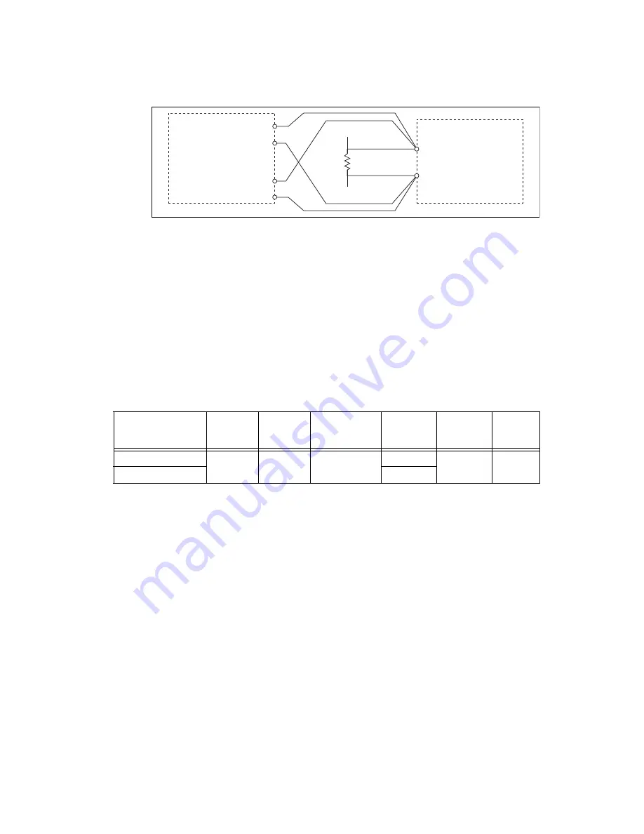
Figure 6.
Quarter-Bridge Accuracy Verification Connections to the NI 9219
2.
Create an AI voltage channel in the 1 V range on the NI 9219.
3.
Commit the task to place the NI 9219 in voltage mode. This prevents the module from interfering
with the resistance measurements of the DMM.
4.
Configure the DMM for a 4-wire resistance measurement in the appropriate range according to the
test point from Table 13.
5.
Enable Auto Zero on the DMM.
6.
Acquire a resistance reading with the DMM. Record this measurement as
ref
.
7.
Disconnect the DMM from the resistor to ensure that the terminals on the DMM do not interfere
with the resistor while the NI 9219 makes measurements.
8.
Clear the task.
9.
Create an AI bridge (V/V) channel on the NI 9219. Configure the channel according to Table 12.
10. Acquire 20 unscaled I32 quarter-bridge readings with the NI 9219. Record the average of the
readings as data
unscaled
.
11. Scale the data by using the formula below to change the unscaled data into
.
where
range
max
is the maximum value for the selected range in Table 13.
12. Perform the following calculation using the recorded
ref
and
channel
values.
Table 12.
NI 9219 Configuration for Quarter-Bridge Accuracy Verification
Measurement Type
Minimum
(V/V)
Maximum
(V/V)
Strain Config
Nominal
Gage
Resistance
ADC
Timing
Mode
Sample
Timing
Type
Quarter-Bridge 350
–0.025
0.025
Quarter-Bridge
350
High
Resolution
On
Demand
Quarter-Bridge 120
120
Ω
Ω
SENSE
HI
LO
HI
LO
R
TestPoint
NI 9219
DMM
HI (3)
LO (5)
Ch
x
channel
data
unscaled
2
24
-----------------------------
range
max
=
Accuracy
channel
ref
–
=


