background image


4


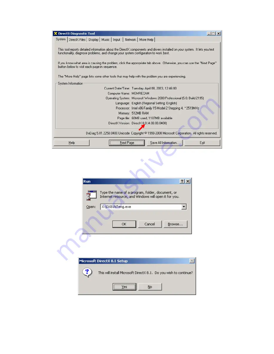
3. From the Start Menu run the DirectX® 8.1 installation file at 

X:\dx81NTeng.exe


where X represents the CD-ROM drive letter for your particular computer.  Click the 
[OK] button. 


4. In the “Microsoft DirectX 8.1 Setup” window click the [Yes] button to begin 
installation. 


5. In the “Microsoft DirectX 8.1 Setup” window read the License Agreement.  Click 
the [Yes] button to accept the agreement. 
 

Summary of Contents for HotShot

Page 1: ...HOTSHOT Version 1 0 User Manual NAC Image Technology Inc Pixoft Diagnostic Imaging Ltd Feb 2005 ...

Page 2: ...ting a Camera 19 Recovering Data from the Buffer 21 Making a Recording 21 Record Controls 22 The Trigger 22 Play Controls 23 View Measure Reticle Functions 24 Image Quality Settings 25 Recorded Information 25 Record Information 26 Saving Out 27 Tools 30 Calibration 30 Reticle 30 Grid 31 Pixel Analysis 32 Pixel Peak 32 Pixel Views 36 Miscellaneous 40 Preferences 40 Start End Trigger Offset 41 Memor...

Page 3: ...crosoft DirectX version 8 1 is required The following steps will guide you through the inspection and update process of DirectX 1 From the Start Menu run the DirectX diagnostic utility with the command dxdiag Click the OK button 2 Inspect which version of DirectX is installed in your computer If the current version is older than DirectX 8 1 continue the update process If DirectX 8 1 or newer is sh...

Page 4: ...X represents the CD ROM drive letter for your particular computer Click the OK button 4 In the Microsoft DirectX 8 1 Setup window click the Yes button to begin installation 5 In the Microsoft DirectX 8 1 Setup window read the License Agreement Click the Yes button to accept the agreement ...

Page 5: ...5 6 Please wait while the DirectX components and drivers are extracted and installed ...

Page 6: ...e OK button to reboot 8 Once Windows restarts verify that DirectX was updated by running the diagnostic utility again From the Start menu run the command dxdiag Click the OK button 9 Verify that DirectX 8 1 is now shown Click the Exit button ...

Page 7: ... PCI boards 1 From Windows Explorer or My Computer look inside the CD Rom and find the install program called HotShotInstall exe 2 In the Welcome window click the Next button 3 In the Choose Destination Location window click the Next button to accept the default target directory ...

Page 8: ... the Next button to backup all replaced files If you do not wish to backup these files click the No radio button and then click the Next button 5 In the Select Program Manager Group window click the Next button to accept the default program folder ...

Page 9: ...n the Start Installation window click the Next button to begin the installation 7 Please wait for the software components to be installed 8 In the Installation Complete window click the Finish button to exit ...

Page 10: ...e Start menu Hardware Installation CAUTION Power down your system before opening the computer case Handle electronic devices with care 1 Remove the computer case cover Install the HotShot PCI Controller in any empty PCI slot on your system board ...

Page 11: ...11 2 Connect the trigger ribbon cable to connector P4 on the HotShot PCI Controller 3 Connect the power cable to the power supply ...

Page 12: ...on the Camera Head Connect P2 on the PCI Controller to P2 on the Camera Head Connect Power on the Power Trigger Panel to Power on the Camera Head Restore the computer case cover Connect Power and turn computer system on External Signal Input Output These two connectors on the camera head are used to synchronise two or more cameras together ...

Page 13: ...talled Please wait while the PCI card is recognized and the Found New Hardware Wizard window appears 1 In the Found New Hardware Wizard window click the Next button 2 In the Found New Hardware Wizard window verify that the Search for suitable driver for my device radio button is selected Click the Next button ...

Page 14: ...14 3 In the Found New Hardware Wizard window check the Specify a location box Click the Next button 4 In the Found New Hardware Wizard window click the Browse button ...

Page 15: ...cw2 inf Select the Epixxcw2 inf file and click to Open button You may however have specified somewhere different when you installed the software In the drivers folder there are also different folders for different operating systems 6 In the Found New Hardware Wizard window click the OK button 7 In the Found New Hardware Wizard window click the Next button ...

Page 16: ...16 8 In the Digital Signature Not Found window click the Yes button ...

Page 17: ... from the Start menu Connections If the installation above was followed correctly the computer is now setup to operate in single camera mode The trigger input on the power trigger back plate needs to be connected to a BNC trigger cable to provide an external triggering to stop start recordings ...

Page 18: ... this The Main Window When the software starts it will look like the screen shot below This window is divided into three areas The first is the video window which is the black area in the top left The area at the bottom is the play and record controls The area on the right is the Main controls and tools The area on the right is split up into 3 tabbed pages called Selection Measure Tools and Pixel ...

Page 19: ...s will then connect the camera and make it ready for use 4 If however there is no camera in the list or another camera is needed enter the new camera information in the camera information boxes and click the Add button This will add the new camera to the list and then tick the box next to the camera s name click the Connect Selected Cameras button This will connect the camera and make it ready for...

Page 20: ...s a colour camera or uses a single monochrome channel if monochrome is chosen Depending on the colour setup of the camera in position 1 will determine which colour setup gets applied to all subsequent cameras 7 The Camera video list controls box will now look like this The status column in the grid will show what tasks the camera is performing while the software attempts to connect it If more than...

Page 21: ...d clean Making a Recording To make a recording do the following after connecting to a camera 1 Select the Memory Segment This box will be filled up with the number of memory segments the board has been made into To change this see below 2 Select recording parameters Use the Record Info to set the Frames per second shutter speed and trigger mode 3 Push the View Arm Button You are in view mode You c...

Page 22: ...ist If you select CUSTOM then you should push the button and then click the image to set the white balance at the clicked pixel Gain Set the Gain Increasing the gain will assist with low light situations but it will begin to introduce noise if used above 6dB Gamma Sets the gamma from with either 1 1 8 or 2 2 Notes once a recording has been made the Record info settings are disabled and cannot be c...

Page 23: ...ut the system into LOOP mode The system will keep looping about the sub range After a recording Step Forwards Step one frame forwards After a recording Fast Forward Jump to the last frame of the recording or the last frame of the sub range see below After a recording VIEW ARM Put the camera s into VIEW or ARM Mode Pushing this button once will put the camera into VIEW Mode A Live image will be dis...

Page 24: ...icking the Mark OUT button After a recording Replay Speed Sets the requested FPS replay speed After a recording Lock Speed Maintains the requested replay speed by skipping frames if necessary After a recording The slider bar below the above button is used to indicate the current position with a thick grey tick running along the bar The red line indicates the trigger frame The triangles below can h...

Page 25: ...separated format to the file specified and displayed on the image with a cross hair This will continue until you depress the reticle button again See below under Tool For more in depth instructions Calibrate and Reticle functions are repeated on the Measure Tools Tab Image Quality Settings Image quality settings are only available AFTER a recording has been made Use this To do this Brightness Adju...

Page 26: ... the SNAP Button 2 Push the Select Button The image will automatically zoom to fit 3 Use your mouse to drag an area of interest 4 When you let go of the mouse button the background will be tinted RED to show you the area of interest selected 5 If you are happy with the selection then click SET 6 If not then Drag again 7 To reset a previously set Area of Interest click the Reset Button There are so...

Page 27: ...tShot Link allows the saving out of recorded images either separately or if there are two cameras in the PC two recorded images can be saved out joined together A comment typed here will be added to the frame information if frame information is included on the image output See Preferences below To save out from a single camera 1 First the range needs to be set of which frames are required to be sa...

Page 28: ...dow will appear asking for a filename and a location 9 Then another window will appear asking if the AVI is to be compressed if so select on in the drop down list and click Ok 10 Now the AVI will be saved out and the progress will be indicated in the progress bar If at anytime the save needs to be stop clicking the Cancel button will stop the saving out To save out two camera s images 1 Select the...

Page 29: ...bove options These options affect how the software operates after it has recorded into to all of memory segments When the last memory segment has been triggered and recorded into if the Automatic Download is checked then the software automatically saves out segments into the required format and range in the pre defined location If the selected file format was BIN Raw binary data direct from the PC...

Page 30: ...he drop down list or enter it manually Click OK when you have finished To reset the calibration to 1 pixel 1 pixel push the reset button Reticle This tool is used to mark the image at specific points of interest There are some options available to aid the user The user can have the software step through to the next frame automatically by checking the Auto Step to Next Frame checkbox then the numbe...

Page 31: ...t set Press the button and then click the image Grid Type Different types of Grid to draw Y is Vertical Lines X is Horizontal Lines Polar will be concentric circles moving out from the Start Position Rotate Rotates the Grid by the degrees set No use for polar grid function Frequency The spacing of the grid lines This value will relate to the calibration If no calibration is performed than it will ...

Page 32: ...ther Pixel Peak The pixel peak group box at the top of the tabbed page allows the pixel values to be extracted from the current images displayed in the video window There are various options to choose from to have a look at a defined area of 11 pixels by 11 pixels 1 Select the Defined Area bullet its default position 2 Then select the 11x11 option in the drop down box This is only enabled when Def...

Page 33: ... below 6 Because the camera is monochrome there will be no colour options it the camera was a colour model there would be the option to view the Red Green and Blue Channels The Grid contains the pixel values at the pixel position marked at the top and left sides To select a different area to peak at click on a new location on the current images ...

Page 34: ...n the edit boxes above The grid will keep updates as long as its window is open closing the window will stop displaying the pixel s values There is another option in the Pixel Peak box Whole Image Size If this option is select the drop down box is disabled Then click the Pixel Peak button will open another window and fill the grid with the whole images pixel s values Note if the image size is big ...

Page 35: ...the area clicked being at the centre display of the grid and the co ordinates being displayed in the edit boxes above A yellow cross hair will appear on the image indicating the co ordinates chosen Note to change the colour used on the image to show the user the area being viewed click the Cross Hair Colour box a colour dialog box will appear and another colour can be chosen The default is yellow ...

Page 36: ...lay that channel in the graphs Row Column Intensity This function extracts from the current frame the pixel values intensity s along a pre selected Row or Column To use 1 Select whether you wish to view a row or column 2 Click the Pick Pixel button 3 Next click on the image of the requested row column 4 A new window will appear and line will be drawn representing the row or column ...

Page 37: ...nother bullet 8 The programme also allows the change of orientation from row to column or vice versa Note for monochrome camera changing the to Red green or blue channels will produce incorrect values choice RGB 3 or use the formula to obtain the correct pixel values Intensity over Time This function can only be carried out after recording It takes the pixel s values depending on what is selected ...

Page 38: ... will change to an hourglass and the programme will run through each frame and decode the selected pixel s value 6 The progress bar will indicate the progress of the function 7 To cancel this function at any time click the Cancel button 8 When the programme has finished gathering the results a new window will open 9 Once the graph is open the window needs to be closed before any other functions ca...

Page 39: ... required by moving the mark IN and mark OUT slider triangles or inputting the frame number direct 4 Clicking the Pick Pixel button 5 The click the pixel on the image which the row or column goes through 6 The progress bar will indicate the progress of the function 7 To cancel this function at any time click the Cancel button 8 When the programme has finished gathering the results a new window dis...

Page 40: ...40 Miscellaneous Preferences The Default Settings button will show the preferences screen ...

Page 41: ...ault folder to save video files to Image Background Colour Sets the colour for the image window Cut Resolution Set the default cut resolution mode Frame Rate Set the Default Frame rate Shutter Set the Default Shutter Trigger Set the default trigger Mode White Balance Set the Default White Balance Start End Trigger Offset Example 1 if you have 100 frames available a start trigger would normal cause...

Page 42: ...ntation settings and update the boxes below These boxes contain the maximum record time in seconds and frames and the available record time in seconds and frames per segment If Auto Increment Memory Segment After triggering is check then once the trigger has been received whilst recording in the current segment the software will automatically jump to the next segment and re arm itself awaiting the...

Page 43: ...ges from the mouse and keyboard The same goes for the trigger watch except that this watches for a state change on the trigger cable to stop recording The higher the trigger watch setting the more time the operating system allocates to check for a state change on the trigger cable So a higher setting will mean a more accurate trigger but with less time processing messages from the keyboard or mous...

Page 44: ...44 About The about box displays the current version and build number underneath and what operating mode the programme is working in 1 Multi Camera 2 Single Camera ...

Reviews: