background image

2201Q4JE-MY-C9-N_2018.01. 

Chapter 7 Related Documents 

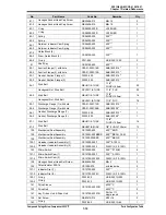
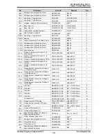
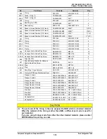
Compound 2-stage Screw Compressor 4032**C


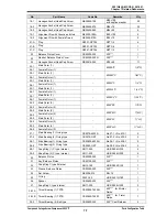
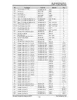
Parts Configuration Table 

7-12


No. 

Part Name 

Code No. 

Remarks 

Q

’ty. 

325 

O-ring 

PA11-070 

JIS B 2401 P70 

326-1 

Gland, O-ring (1) 

CS32600-400 

400V** 

326-2 

Gland, O-ring (2) 

CS32600-320 

320*** 

328 

O-ring 

PA11-058 

JIS B 2401 P58 

346 

Shaft Key for TPTB 

CS34600-400 

400*** 

419 

Backup Ring 

PBP21-070 

SUN-2BP-70-T2 

420 

Spacer, Unload Position (30 % load) 

CS42000-320S30 

320S**   

1(*SC) 

420 

Spacer, Unload Position (30 % load) 

CS42000-320M30 

320M**   

1(*MC) 

420 

Spacer, Unload Position (30 % load) 

CS42000-320L30 

320L**   

1(*LC) 

420 

Spacer, Unload Position (30 % load) 

CS42000-320LL30 

320LL*   

1(*LLC) 

421 

O-ring 

PA11-058 

JIS B 2401 P58 

432-1 

O-ring 

PA12-200 

JIS B 2401 G200 

432-2 

O-ring 

PA12-165 

JIS B 2401 G165 

433-1 

O-ring 

PA12-200 

JIS B 2401 G200 

433-2 

O-ring 

PA12-165 

JIS B 2401 G165 

594 

Hexagon Socket Head Cap Screw 

NB35420-075 

M20×75 

12 

595-A 

Hexagon Socket Head Cap Screw 

NB35424-110 

M24×110 

10 

595-B 

Hexagon Socket Head Cap Screw 

NB35420-110 

M20×110 

596 

Alignment Pin 

NE2316-065A 

Φ16×65 

597 

Special Spring Washer for Hexagon 
Socket Head Cap Screw 

ND330-06 

No.3 6 

605-A 

Plug 

NF021-NPT03 

NPT3/8 

605-B 

Plug 

NF021-NPT010 

NPT1 1/4 

661 

Snap Ring C type External 

NG12-070 

JIS B 2804 S70 

674 

O-ring for BOD type Mechanical Seal 

PA62-039 

AS568A 261 

Flange, Oil drain 

CZA01-300C0004B 

ANSI #300 1/2" 

Flange, Oil drain 

CZA01-300C0004B 

ANSI #300 1/2" 

Flange, Oil drain 

CZA01-300C01B 

ANSI #300 1" 


Flange Gasket, Oil drain 

CZA01-300C0004B 

ANSI #300 1/2" 


Flange Gasket, Oil drain 

CZA01-300C0004B 

ANSI #300 1/2" 


Flange Gasket, Oil drain 

CZA01-300C01B 

ANSI #300 1" 


Stud Bolt 

CZA01-300C0004B 

1/2" -13UNC×60mm 


Stud Bolt 

CZA01-300C0004B 

1/2" -13UNC×60mm 


Stud Bolt 

NBU605/8-11UNC 

5/8" -11UNC×75mm 


Hexagonal Nut 

NCU1501/2-13UNC 

1/2" -13UNC 


Hexagonal Nut 

NCU1505/8-11UNC 

5/8" -11UNC 


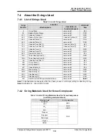
The part code of the O-ring is the one assigned to NBR which is standard material. 
When the material of the O-ring is other than NBR, a different part  code is used for 
each material. 
If you are using O-rings made from other than the standard material, please contact 
MAYEKAWA when placing an order. 


Summary of Contents for 4032**C Series

Page 1: ...032SMC 4032SSC CAUTION Before operating servicing or inspecting this product read this manual thoroughly to fully understand the contents Keep this Instruction Manual in a safe designated place for fu...

Page 2: ...1 4032LLC B 51 4032LLC B 61 4032LMC B 51 4032LMC B 61 4032LSC B 51 4032LSC B 61 4032MLC B 51 4032MLC B 61 4032MMC B 51 4032MMC B 61 4032MSC B 51 4032MSC B 61 4032SLC B 51 4032SLC B 61 4032SMC B 51 403...

Page 3: ...escribed below Malfunctions damage or deterioration of this product due to abnormal or improper use including improperly storing this product outdoors or under too hot humid conditions unexpected insp...

Page 4: ...volved and measures to avoid danger Do not allow any person other than those educated on the fundamental expertise of this product and trained about hazards involved and measures to avoid dangers to a...

Page 5: ...reproduced into any electronic medium or machine readable form without prior permission from MAYEKAWA Photographs or drawings included in this manual may differ from the appearance of actual product...

Page 6: ...Do s about Personal Protective Gear 1 2 1 1 1 5 Do s about Handling of Hazardous and Toxic Substances 1 2 1 1 1 6 Do s about Handling Emergency Situations 1 2 1 1 1 7 Do s about Waste Oil Fluid and Ma...

Page 7: ...Protection of the Compressor 3 6 3 2 6 Airtightness Test 3 7 3 2 7 Lubricating Oil Charge 3 7 3 2 7 1 Initial Charge of Lubricating Oil 3 7 3 2 7 2 Additional Charge of Lubricating Oil 3 7 3 2 8 Char...

Page 8: ...r Cover 5 16 5 4 2 1 Disassembly 5 16 5 4 2 2 Inspection 5 17 5 4 3 Unloader Piston and Unloader Cylinder 5 18 5 4 3 1 Disassembly 5 18 5 4 3 2 Inspection 5 19 5 4 4 Shaft Seal Block 5 20 5 4 4 1 Disa...

Page 9: ...tors 5 39 5 5 5 Suction Cover and Side Bearings 5 40 5 5 6 Installing the Suction Cover 5 41 5 5 7 Balance Piston and Balance Piston Sleeve 5 42 5 5 8 Thrust Bearing Block 5 43 5 5 8 1 High stage Bloc...

Page 10: ...cal seal 6 7 10 Capacity control position is indicated incorrectly 6 7 11 Capacity control malfunction 6 8 12 Compressor generates abnormal vibration and or sound 6 9 Chapter 7 Related Documents 7 1 E...

Page 11: ...ore performing the work together with at least one other person thoroughly confirm each other s work details and procedures to acknowledge the other worker s movement When troubleshooting during opera...

Page 12: ...ear any neckties or jewelry as there is a risk of being entangled by a movable part or rotating part Put on a helmet as your hair may get entangled Do not have anything in your pocket to prevent objec...

Page 13: ...s described in this manual warn dangerous situations that may arise during work by using the following four categories Neglecting such warnings may cause accidents resulting in personal injury or even...

Page 14: ...ures below 40 C E Compressor high stage side discharge casing and discharge piping Refer to Figure 1 1 Burn injury due to contact Contact with or inhalation of hazardous substances generated by leakag...

Page 15: ...2201Q4JE MY C9 N_2018 01 Chapter 1 Safety Compound 2 stage Screw Compressor 4032 C 1 3 Residual Risks 1 5 Figure 1 1 Locations of Hazardous Sources compressor...

Page 16: ...erating procedures for the emergency stop button i e how to stop the operation and restore the normal operating condition must be clearly defined and the information provided to the user of this produ...

Page 17: ...intermediate pressure IP This device activates when the intermediate pressure of the compressor gets equal to or higher than the set value and properly controls the compressor In some cases this devic...

Page 18: ...protective devices require operation tests and confirmation of the settings calibration before commissioning as well as at regular intervals Specify the inspection methods intervals of the compressor...

Page 19: ...stems the 4032 C model has been used in variety process gas compression systems due to the ability to meet various requirements specifications i e temperature conditions pressure conditions power cond...

Page 20: ...ct mass of 4032XLLLC is a data of the specifications for cast steel casings Table 2 2 4032 C Screw Compressor Specifications 2 2 Items Model L S C M L C M M C M S C S L C S M C S S C Product mass kg 9...

Page 21: ...tion temperature C 60 Maximum low stage discharge temperature C 90 Maximum high stage discharge temperature C 100 Maximum oil supply temperature C 60 Minimum oil supply temperature C 30 Maximum male r...

Page 22: ...Q4JE MY C9 N_2018 01 Chapter 2 Compressor Specifications and Structure Compound 2 stage Screw Compressor 4032 C 2 3 Compressor Specifications 2 4 2 3 3 Outer Dimensions Figure 2 1 Outer Dimensions 403...

Page 23: ...et port 1 ANSI 300 2 F7 Low stage Side bearing lubricating oil inlet port 1 ANSI 300 1 F8 Oil injection inlet port 1 ANSI 300 2 1 2 F9 High stage journal lubricating oil inlet port 1 ANSI 300 2 F10 Oi...

Page 24: ...6 1031 1031 1031 L16 1279 1279 1279 1171 1171 1171 1056 1056 1056 L17 1336 5 1336 5 1336 5 1228 5 1228 5 1228 5 1113 5 1113 5 1113 5 L18 1785 5 1785 5 1785 5 1677 5 1677 5 1677 5 1562 5 1562 5 1562 5...

Page 25: ...15 15 15 15 15 W22 160 160 160 160 160 160 160 160 160 W23 700 700 700 700 700 700 700 700 700 W24 605 605 605 605 605 605 605 605 605 H1 550 550 550 550 550 550 550 550 550 H2 30 30 30 30 30 30 30 3...

Page 26: ...ds by bearings They are meshed with each other in a joint assembly These two screw rotors are a set of a male rotor having 4 protruding lobe profiles M rotor and a female rotor having 6 concave lobe p...

Page 27: ...male rotor or M rotor and the rotor having 6 concave lobe profiles is called a female rotor or F rotor In this manual they are referred to as M rotor and F rotor The compressor is driven by the motor...

Page 28: ...Volume Ratio Vi Volume ratios Vi of C series screw compressors are indicated in performance tables or catalogs by using port symbols L and M The volume ratio represented by each symbol is as follows L...

Page 29: ...Specifications and Structure Compound 2 stage Screw Compressor 4032 C 2 5 Mechanisms 2 11 A Properly adapted Vi to load condition B Improperly adapted Vi to load condition Figure 2 8 Relationship bet...

Page 30: ...direction the low stage compressor uses tilting pad bearings while the high stage compressor uses angular ball bearings in the front combination In case of API 619 compliance is required and or specia...

Page 31: ...compressor compressed at the low stage side 2 and then discharged at 3 3 and 4 are connected with a pipe At the mid point of the pipe that gas is mixed with the gas from liquid cooler which was used f...

Page 32: ...low to the shaft seal block lubrication After completing each role the oil flows to the high stage via the low stage rotor messing part Oil supply system in the high stage is split into three flows Ev...

Page 33: ...her regulations requirements Before installing the compressor please read this chapter and related documents attentively and fully understand their contents Electrical works should be performed only b...

Page 34: ...ess the signals such as calling out or hand signals are completely understood by the workers at site 9 Slowly reel up the wire ropes until immediately before the compressor leaves the ground 10 Then r...

Page 35: ...9 N_2018 01 Chapter 3 Installation Compound 2 stage Screw Compressor 4032 C 3 2 Installation Works 3 3 Outer Dimensions Mass and Lifting Position Figure 3 1 Outer Dimensions Mass and Lifting Position...

Page 36: ...00 8 381 330 270 200 50 7 8 9 12 Lubricating oil inlet for low stage TPTB ANSI 300 2 165 127 92 50 35 5 8 11 8 Lubricating oil inlet for low stage main bearing ANSI 300 2 170 127 92 40 35 5 8 11 8 Lub...

Page 37: ...the rotating shaft At the time of turning ON OFF each electric power breaker make sure to prevent electric shock For shaft alignment work between the compressor and driving machine use designated tool...

Page 38: ...ng to problems Do not let the mass of the piping connected to the compressor applied onto flanges or joints Be sure to prepare proper supports for piping 3 2 5 4 Equipment and Devices for Protection o...

Page 39: ...ation and operating condition specify the procedure method and amount of the initial charge of lubricating oil and make sure to provide users of this product with such information In determining the p...

Page 40: ...operation of the compressor under some operating conditions On the contrary if the refrigerant does not dissolve in the oil or the oil and refrigerant are non inter soluble the viscosity may become t...

Page 41: ...Glycol PAG PAG oil is much more hygroscopic than mineral oils and any moisture mixed in the oil may lead to rust corrosion and wear within the package When handling PAG oil pay special attention to th...

Page 42: ...10 from that of fresh oil d Water content 2000 mass ppm or less Note1 e Degree of contamination Degree of contamination measured by mass method Millipore value shall be 15 mg 100 mL or less Table 4 2...

Page 43: ...e analysis that the criteria given in Tables 4 1 to 4 3 are not satisfied the oil must be replaced 4 1 5 2 During Normal Operation Lubricating oils will degrade gradually as the system is operated ove...

Page 44: ...hange performance If the vacuum pumping performed upon initial installation or maintenance is insufficient or the suction pressure is lower than the atmospheric pressure to suck air if the suction pip...

Page 45: ...perform the following checks every month Operate the oil pump for 10 seconds per week After that rotate the compressor shaft 10 rotations or more Measure the system pressure once per month Check for r...

Page 46: ...arting the work When using lifting devices e g a crane etc and or lifting tools ensure that they can sufficiently withstand the load When lifting a heavy load object do not allow anyone s body to put...

Page 47: ...ng those tools smeared with oil increases the risk of slip and fall leading to an injury Also during the service there is a risk of foreign matters intruding inside the compressor to cause its damage...

Page 48: ...from the normal pressure during rated operation If the pressure is too high or too low check the conditions of the high low stages Discharge pressure MPa Difference from the condensation pressure for...

Page 49: ...n the operating hours of the compressor from the initial operation starting has exceeded 500 hours If the filter used is a temporary filter for initial operation remove the filter Also as it is common...

Page 50: ...differential pressure across the suction strainer is high Yearly inspection and cleaning Lubricating oil Analyze the oil after 500 hours of initial operation Replace the oil if the analysis result doe...

Page 51: ...e operating conditions Refrigeration 5 years or 40 000 hours Relatively variable operating conditions Ice making and chilling 4 years or 30 000 hours Frequent start stop and relatively variable operat...

Page 52: ...tools for the compressor by referring to Section 7 5 Disassembly Tools in this manual Chapter 7 In addition prepare other necessary tools and materials including general hand tools GC grinding stones...

Page 53: ...s found 2 39 2 Lock Nut 2 AN21 NG31 021 2 40 1 Lock Washer 1 AW28X NG32 028x 2 40 2 Lock Washer 2 AW21 NG32 021 2 63 1 O ring JIS B 2401 G250 PA12 250 1 63 2 O ring JIS B 2401 G240 PA12 240 1 65 1 O r...

Page 54: ...t Lubricating Oil Inlet Flange 1 Main PL300 050 ANSI 300 2 1 216 1b Gasket Lubricating Oil Inlet Flange 1 Side PL300 025 ANSI 300 1 1 216 1c Gasket Lubricating Oil Inlet Flange TPTB PL300 050 ANSI 300...

Page 55: ...id at the receiver In using either method prepare a working flow sheet of the system beforehand Check the valves to be controlled during the recovery work according to the method to be used by compari...

Page 56: ...crease controls 4 Electric wiring for capacity control operation In some cases the unloader indicator assembly may be removed without removing the wiring Refer to Section 5 4 1 1 in this chapter 5 Com...

Page 57: ...ressor place the compressor on a special stand as shown in following Figure 5 1 and then remove eight or more hexagon head cap screws around the bottom flange part Never try to remove these bolts whil...

Page 58: ...dation when the compressor is operated after the reassembly Please fully understand the following sections before starting the work In general the disassembly sequence will follow the flow shown on th...

Page 59: ...de to be easy to see the indicator dial the standard indicator assembly is attached with a fixture for 4032 C model that bends the indicator by 90 clockwise or counterclockwise viewed from either of t...

Page 60: ...ic plate on the terminal block and then remove the wiring Apply vinyl insulation tape to the wiring terminals and paint identification numbers to prevent them from being mixed up at recovery When remo...

Page 61: ...1 67 2 This block structure of the low stage and the high stage is the same but there is only one different point that the low stage hexagon socket head cap screw 81 1 which fastens the bearing gland...

Page 62: ...ng ring 79 1 79 2 attached to the shaft c 3 Inside the unloader cover the spring retainer 84 1 84 2 spring 83 1 83 2 and then V ring 82 1 82 2 are assembled in this order Because the V ring is tightly...

Page 63: ...age unloader cylinder 30 indicated load unloader spacer is installed to prevent an abnormally high intermediate pressure at the time of compressor start up Figure 5 6 Unloader Cylinder Block 5 4 3 1 D...

Page 64: ...cover with balance piston cover by six long hexagon head cap screws 62 The high stage unloader cylinder is to be pulled out similarly to Step e for the case of low stage cylinder However if the cylind...

Page 65: ...er For disassembly and assembly work of these mechanical seals a qualified trained personnel and special tools are required For details contact us 5 4 4 1 Disassembly After removing the hexagon socket...

Page 66: ...yebolts into the thread holes on the upper bearing cover and keep lifting using lifting tools and a crane or like tools e From the back facing holes on the bearing cover flange surface removed the unl...

Page 67: ...he drive side and driven side of the coupling can be separated along the shaft axis move the main body exactly along the shaft axis to separate them 5 4 7 Gear Coupling The gear coupling which is used...

Page 68: ...lance piston key 31 it is unnecessary to remove the key In addition to prevent rotation of the balance piston sleeve 33 spring pin 34 is used in this models it is unnecessary to remove the pin c Remov...

Page 69: ...Remove the hexagon head bolts 45 1 with spring washers 46 1 fastening the thrust bearing gland 43 1 and then remove the O ring 150 1 and thrust bearing gland The thrust bearing gland may not be remov...

Page 70: ...of the suction cover by spraying air or like b We recommend unconditional exchange of the side bearings on the occasion of the compressor overhaul but for confirmation of the compressor condition and...

Page 71: ...upport the main rotor casing Moreover hook up the eyebolts of the high stage suction cover to the lifting tools of a crane or the like e Loosen and remove the hexagon socket head cap screws 2 2 securi...

Page 72: ...een loosened Then remove the torsional slip washer 237 2 lock washer 40 2 and thrust washer 250 2 b The clearance fit is applied to two gaps between the outer race of the thrust bearing and the bearin...

Page 73: ...he conditions You could feel some irregular click even with a small f foreign matter that has entered during the removal process In such a case it should return to the normal condition when high press...

Page 74: ...e surfaces of the tilting pad and the thrust collar If any flaw and or abrasion is found in each tilting pad piece it is necessary to replace the TPTB assembly with a new one If a flaw of the thrust c...

Page 75: ...t surface in the direction perpendicular to the shaft axis If any such flaw is found use a fine sandpaper or grindstone to smooth the surface b In case of ammonia refrigerant or gas compressor the non...

Page 76: ...further disassembly is required e The guide block stem 88 2 is screwed in from the bottom of the main rotor casing and the guide block 87 2 is engaged from the top To replace the O rings 89 2 remove...

Page 77: ...or casing then screw the bolts evenly to push and separate the bearing head and the main rotor casing d Separate them carefully along the shaft axis as the unloader push rod 67 1 is engaged e The main...

Page 78: ...he reverse of the disassembly sequence First of all clean the work bench and the tools to be used Immediately prior to the assembly use washing agent e g kerosene parts cleaner to clean the parts to b...

Page 79: ...2201Q4JE MY C9 N_2018 01 Chapter 5 Maintenance and Inspection Compound 2 stage Screw Compressor 4032 C 5 5 Reassembly 5 34 Figure 5 16 Illustration of the Assembly Sequence Example...

Page 80: ...the assembly mount the assembly in the main rotor casing using a crane or like In the high stage side slowly push in the slide valve while aligning the groove of the slide valve with the guide block...

Page 81: ...use a tool such as a guide bar as a red arrow shown in the right picture b After the bearing has been inserted install the internal snap ring 29 to retain the bearing in position Securely install the...

Page 82: ...erefore either use a pedestal as used in the disassembly process or lift the main rotor casing using a crane or other device to align the centers c After lightly fastening two bolts drive in the align...

Page 83: ...backup rings 419 alternately on the two O ring grooves in the O ring gland inner circumference h Also attach the O ring 9 on the O ring groove of the O ring gland outer circumference i Then mount the...

Page 84: ...rked on the lobe tip the M rotor has the marking on the discharge side and the F rotor has the marking on the suction side a Apply sufficient amount of lubricating oil on the main bearing in the beari...

Page 85: ...check that the notch position of the bearing is at the pin position If the position has been shifted pull out the bearing and try the press fitting process again Similarly to installing the main beari...

Page 86: ...along the shaft axis to engage the rotor shafts with the side bearings At this time be careful not to damage the inside surface of the side bearing by the shaft end As the low stage unloader push rod...

Page 87: ...chamfered side of the balance piston sleeve towards the O ring already placed Also align the notch of the balance piston sleeve to the spring pin 34 for rotation stop and to the oil supply port c Inse...

Page 88: ...et head cap screw 12 46 2 Conical spring washer 2 8 45 1 Hexagon socket head cap screw 1 12 45 2 Hexagon head bolt 2 8 The torsional slip washer 237 and lock washer 39 must be replaced with new ones I...

Page 89: ...achine Then use a blue whetstone to write the above V marking on the bearing to show the inside direction of the machine Then install the bearing above picture c After the thrust bearing has been inst...

Page 90: ...pply protective tape or like on the M rotor axis portion installing the shaft seal beforehand b Confirm the marking M F of the thrust bearing alignment spacer 42 1 and install them with the same combi...

Page 91: ...an be pushed to the discharge side by tapping with cushion like Teflon block not striking the rotor shaft end directly but the same method cannot be applied to the low stage Manufacturing and preparin...

Page 92: ...to make the thrust bearing alignment spacer 42 thinner by the amount of the end clearance difference between the measured and specified values After the surface grinding is done use a micrometer to m...

Page 93: ...piston 64 2 and then install the cap seal 66 2 on it It can be smoothly installed by slightly folding the cap seal along the circumferential direction Also using a small and smooth spatula will facili...

Page 94: ...e hexagon socket head cap screws 18 1 and evenly tighten them to reduce the clearance and make the cover contact the body Then tighten all the bolts at the specified torque g There are two types of th...

Page 95: ...O ring and cap seal in the unloader cylinder 60 1 The work procedure is the same as that for the high stage side as described in Section 5 5 9 item i d In case of 4032 C the O ring 63 1 for sealing be...

Page 96: ...The orientation of the V ring must be such that the apex of the V shape faces the outside and the lips face inside d Install the spring 83 and the spring retainer 84 into position Then insert the shaf...

Page 97: ...e low stage M rotor shaft is rotated clockwise and counterclockwise alternately for a small amount h Once the gear coupling has been successfully engaged push the high stage block onto the low stage b...

Page 98: ...dentical to the one used in a standard single stage compressor except that the dial and micro switch cam which are exclusively designed for 4032 C high stage for the range of 30 to 100 On the low stag...

Page 99: ...remove the indicator glass and check that the micro switch screws 126 are not loosened c Check that the hexagon socket head set screw 128 securing the micro switch cam 127 are not loosened d After ch...

Page 100: ...ips Screw M3 25 4 140 Phillips Screw M3 10 1 127 Micro switch cam 30 to 100 1 141 Indicator glass 1 127 Micro switch cam 0 to 100 1 142 Indicator glass spacer 1 128 Hexagon socket set screw M4 8 1 143...

Page 101: ...lowly to sense capacity control of 0 due to defective capacity control oil supply line Improper adjustment of oil flow control valve throttled excessively Readjust Leak clogging in piping or solenoid...

Page 102: ...caused not by the refrigeration cycle but by the motor Refer to the instruction manual of the motor 03 Unusually low pressure decrease of suction pressure Direct cause Root cause Action Refer to direc...

Page 103: ...ion pressure Heat load on load side is higher than design value Inspect the conditions on load side warehousing volume opening closing of doors etc and take necessary measures Malfunction of suction p...

Page 104: ...ke necessary actions Inspect water supply routes and or mechanisms and take necessary actions If frozen take measures such as improvement of heat insulation or increase of temperature Deficiency in he...

Page 105: ...ide warehousing volume opening closing of doors etc and take necessary measures Failure of low pressure protection device pressure sensor relay etc Identify defective devices investigate causes of fai...

Page 106: ...e replace the defective part Overheated operation See the causes in item 02 Insufficient refrigerant flow Oil supply temperature is high See the causes in item 07 Oil supply temperature is high Machin...

Page 107: ...ause Root cause Action Inaccurate reading of compressor indicator gauge Screw for securing indicator needle is loose Manually operate the compressor s capacity control to indicate 0 position and tight...

Page 108: ...eriorated over time replace If the symptom is caused by wet with water etc remove the cause s and then replace defective part s For details refer to the instruction manual of solenoid valve Internal l...

Page 109: ...ion or if on site overhaul only has been repeatedly performed for a long time this may be the cause Overhaul the compressor at a place where a dynamic balance measurement adjustment system is availabl...

Page 110: ...revent rapid changes Otherwise make adjustment by throttling the aperture of the capacity control increase side oil quantity adjusting valve Expansion valve aperture control cannot keep up with rapid...

Page 111: ...ck Refer to causes of Liquid flow back during startup and Liquid flow back during operation in item 12 Entry of foreign substances Refer to causes of Foreign substances entering the compressor above E...

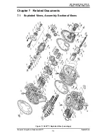
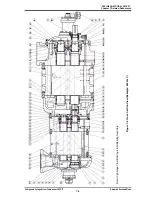
Page 112: ...9 N_2018 01 Chapter 7 Related Documents Compound 2 stage Screw Compressor 4032 C Exploded Views 7 1 Chapter 7 Related Documents 7 1 Exploded Views Assembly Sectional Views Figure 7 1 4032 C Exploded V...

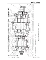
Page 113: ...2201Q4JE MY C9 N_2018 01 Chapter 7 Related Documents Compound 2 stage Screw Compressor 4032 C Exploded Views 7 2 Figure 7 2 4032 C Exploded View High stage...

Page 114: ...2201Q4JE MY C9 N_2018 01 Chapter 7 Related Documents Compound 2 stage Screw Compressor 4032 C Assembly Sectional Views 7 3 Figure 7 3 Assembly Longitudinal Section View Example 4032LLC...

Page 115: ...C9 N_2018 01 Chapter 7 Related Documents Compound 2 stage Screw Compressor 4032 C Assembly Sectional Views 7 4 Note High stage Trust Bearing is Ball Bearing Assembly Figure 7 4 Cross Section View Exam...

Page 116: ...18 01 Chapter 7 Related Documents Compound 2 stage Screw Compressor 4032 C Assembly Sectional Views 7 5 Note High stage Trust Bearing is Tilting Pad Thrust Bearing Assembly Figure 7 5 Cross Section Vi...

Page 117: ...ye Bolt NB600 30 M30 2 5 1 Suction Cover 1 CS00501 4032C1 4032 C 1 5 2 Suction Cover 2 CS00501 4032C2 4032 C 1 6 1 Gasket Suction Cover 1 CS00600 4032CN 4032 C 1 6 2 Gasket Suction Cover 2 CS00600 320...

Page 118: ...032XL C 1 XL C 26 1 Female Rotor 1 25 2 Male Rotor 2 4032 SC 1 SC 26 2 Female Rotor 2 25 2 Male Rotor 2 4032 MC 1 MC 26 2 Female Rotor 2 25 2 Male Rotor 2 4032 LC 1 LC 26 2 Female Rotor 2 25 2 Male Ro...

Page 119: ...de Valve 1 1 L Port CS05400 4032M1L 4032M C 1 M C 54 1 Unloader Slide Valve 1 1 M Port CS05400 4032M1M 4032M C 1 M C 54 1 Unloader Slide Valve 1 1 L Port CS05400 4032L1L 4032L C 1 L C 54 1 Unloader Sl...

Page 120: ...LC 68 1 Guide Pin 1 NE2506 016 6 16 1 68 2 Guide Pin 2 NE2506 016 6 16 1 69 1 Lock Nut 1 NG31 010 AN10 2 69 2 Lock Nut 2 NG31 010 AN10 1 70 1 Lock Washer 1 NG32 010 AW10 1 70 2 Lock Washer 2 NG32 010...

Page 121: ...C 16 95 1 Discharge Flange 1 with hole CZA01 300C12B ANSI 300 12 1 95 2 Discharge Flange 2 with hole CZA01 300C08B ANSI 300 8 1 96 1 Gasket Discharge Flange 1 PL300 300 ANSI 300 12 1 96 2 Gasket Disch...

Page 122: ...ication Oil Supply 2 to Journal CZA01 300C02B ANSI 300 2 1 215 2 Flange Lubricating Oil Supply 2 to TPTB CZA01 300C01B ANSI 300 1 1 216 1a Flange Gasket Lubricating Oil Supply 1 to Main Journal PL300...

Page 123: ...xagon Socket Head Cap Screw NB35420 110 M20 110 2 596 Alignment Pin NE2316 065A 16 65 2 597 Special Spring Washer for Hexagon Socket Head Cap Screw ND330 06 No 3 6 3 605 A Plug NF021 NPT03 NPT3 8 3 60...

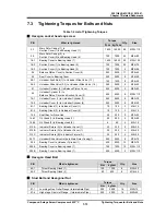
Page 124: ...ver 2 450 4500 6 M20 110 76 1 Unloader Cover 1 to Unloader Cylinder 1 640 6400 8 M22 70 76 2 Unloader Cover 2 to Unloader Cylinder 2 240 2400 8 M16 40 81 1 Bearing Gland 1 to Unloader Cover 1 10 100 3...

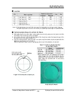
Page 125: ...to turn Take care not to over tighten b Put a mark on the lock nut at the right side edge of the rotor groove where the stopper tongue of the lock washer fits in as shown in Figure 7 9 c From this ma...

Page 126: ...e as left G210 89 2 Guide block Stem 2 same as left P24 150 1 Thrust Bearing Gland 1 same as left G290 150 2 Thrust Bearing Gland 2 same as left G220 163 Unloader Push Rod 1 same as left G65 325 O rin...

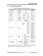
Page 127: ...ring pliers Internal RT 4 SG312 04 Eye bolt M8 200 two peace set UHT0016 Allen wrench key Across flats 1 5 mm 2 mm SG241 02 4 mm SG241 04 5 mm SG241 05 6 mm SG241 06 8 mm SG241 08 10 mm SG241 10 12 m...

Page 128: ...2201Q4JE MY C9 N_2018 01 MAYEKAWA MFG CO LTD 3 14 15 Botan Koto ku Tokyo 135 8482 JAPAN TEL 81 3 3642 8181 FAX 81 3 3643 7094 URL http www mayekawa com...

Reviews: