2201Q4JE-MY-C9-N_2018.01.
Chapter 5 Maintenance and Inspection
Compound 2-stage Screw Compressor
4032**C
5.5 Reassembly
5-45
5.5.8.2 Low-stage Block
The TPTB (Tilting Pad Thrust Bearing) is used as the low-stage thrust bearing. The TPTB for M rotor
and the TPTB for F rotor are the same in outer diameter and inner diameter, but are different in
lengths. The M rotor TPTB is longer than the F rotor TPTB because M rotor thrust load is larger than F
rotor thrust load.
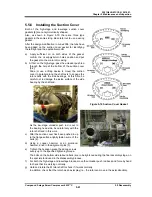
Check the End Play
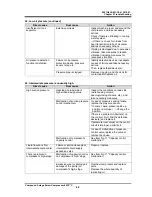
Before assembling this block, measure the end play of the TPTB. When putting the TPTB on the flat
and smooth top of the work bench, the end face of the thrust collar rises up as shown below left picture.
Then, putting the TPTB on a pedestal which has a larger inner diameter hole than a outer diameter of
the thrust collar, the thrust collar falls in the pedestal hole as shown below right picture.
We call this amount of movement of the thrust collar end face as the end play. If this value (end play) is
not within the specified range as shown in Table 5-10, the TPTB can not to be used. Record the
measurement value.
Table 5-10 Specified Value of End Play
Assembly
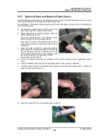
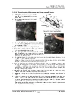
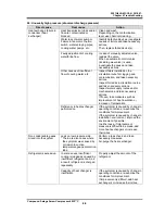
a) Apply protective tape or like on the M rotor axis portion
installing the shaft seal beforehand.
b) Confirm the marking M/F of the thrust bearing alignment
spacer [42-1], and install them with the same combination
when disassembled. There is a specific installing direction
of the thrust bearing alignment spacer. The larger
chamfering side is on the machine side, and the smaller
chamfering side is on the thrust bearing side.
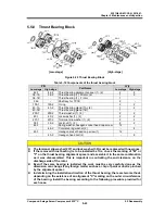
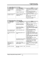
c) Attach a lifting eye bolt on the top of the TPTB in the same
manner at the time of disassembling, and install the TPTB
while lifting by a crane or like lifting device. Using two
eye bolts and pushing with them will make the work easier.
At this time, align the detent protrusion of the TPTB (as
shown a red arrow in right above picture) beneath.
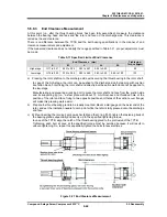
d) Attach the shaft key [346] for the TPTB.
e) After installing the TPTB, install the thrust washer [250-1],
lock washer [40-1], and torsional slip washer [237-1].
Then, tighten the lock nut [39-1] with the specified range
of lock nut tightening angle to secure the thrust collar of
the TPTB on the rotor shaft.
Note: In case of using the TPTB for the high-stage, align the
protrusion of the TPTB just above.
In addition, the thrust washer is not installed to the
high-stage.
Using for
Specified Value
Low-stage M rotor
0.30 - 0.39 mm
Low-stage F rotor
0.25 - 0.34 mm
High-stage
in case of TPTB
0.20 - 0.25 mm


