2201Q4JE-MY-C9-N_2018.01.
Chapter 2 Compressor Specifications and Structure
Compound 2-stage Screw Compressor 4032**C
2.4
Compressor Structure
2-8
2.4
Compressor Structure
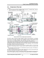
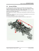
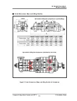
For names of each part of the compressor, refer to Section 7.1 "Exploded Views, Sectional
Views ", and Section 7.2 "Parts Configuration Table".
Figure 2-2 4032**C Screw Compressor Sectional View
The 4032**C model, a compound 2-stage compressor, consists of two compressors, (i) a low-stage
compressor which suctions gas, working fluid, from the refrigerating unit and compresses (pressure-raises)
the gas and (ii) a high-stage compressor which furthermore compresses the gas that has been
pressure-raised by the low-stage compressor and sends the resulting gas to the equipment side.
In each casing (low-stage, high-stage), two screw rotors are supported on both ends by bearings. They are
meshed with each other in a joint assembly. These two screw rotors are a set of a male rotor having 4
protruding lobe profiles (M rotor) and a female rotor having 6 concave lobe profiles (F rotor). They conduct
compressing according to the mechanism explained below.
The standard compressor's M rotor is driven by a 2-pole motor; it operates at 3000 min
-1
(50 Hz) or 3600
min
-1
(60 Hz). F rotor operates at 2000 min
-1
(50 Hz) or 2400 min
-1
(60 Hz), conforming to the operation of M
rotor.
* The actual speed of a motor is less than its calculated speed (synchronous speed). This difference is
caused by slipping of the motor rotor.
The shaft of the low-stage compressor's M rotor which is linked with the motor has a shaft seal block that
keeps gas and lubricating oil from leaking from inside the compressor.
For high efficient operation, the 4032**C model has a capacity control mechanism for coping with load
change on the low-stage, and a capacity control mechanism for reducing startup load on the high-stage.

