2201Q4JE-MY-C9-N_2018.01.
Chapter 5 Maintenance and Inspection
Compound 2-stage Screw Compressor 4032**C
5.3 Compressor Disassembly Preparation
5-7
5.3
Compressor Disassembly Preparation
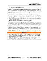
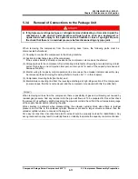
Although screw compressors are very reliable machines, it is still necessary to perform overhaul to
inspect internal parts after a certain period of operation.
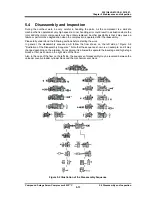
This chapter 5 explains the essential points of disassembly methods, where to inspect on parts, and
reassembly procedure of the compound 2-satge screw compressor 4032**C.
In principle, overhauling of the screw compressor that require complete disassembly should be
performed in the maintenance factory. If you must do the overhaul work at the installation site due to
unavoidable reasons, use the methods described in the following paragraphs.
However, please note that regular overhaul work requires removal of the compressor from the base
frame. And then, the compressor should be placed on a work bench which has properly size area to
disassembling the compressor.
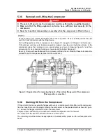
When moving the compressor from the unit base to the workbench, be sure to follow the instructions
given in Chapter 3, Section 3.1 "General Installation Precautions" and Section 3.2.3 "Transfer" of this
manual.
Note that some parts name given in the text of this manual is followed by a number enclosed in square
brackets [ ], which indicates the part identification number given in assembly sectional views or
Exploded views.
5.3.1 Disassembly Tools and Workplace
Prepare necessary disassembly tools for the compressor by referring to Section 7.5 "Disassembly
Tools" in this manual Chapter 7.
In addition, prepare other necessary tools and materials including general hand tools, GC grinding
stones, sandpapers of #80 to #100, about #400 to #800 sandpapers, parts cleaner, lubricating oil,
oilcan, empty can to receive drain oil, waste, etc.
If the overhaul work is to be done with the compressor removed from the installation base, prepare the
work bench whose size is at least around 1.5 times the length and the width of the compressor.
In addition, a special stand for the compressor is required in order to safely perform the removal /
fastening of bolts and plugs on the bottom side of the compressor. Refer to Section 5.3.5 of this
chapter.
To the extent possible, choose a dry and clean workplace free from sand or dust. Note that a sufficient
space is required for the workplace. In addition, iti is necessary a temporary storage place for
disassembled parts .
5.3.2
Replacement Parts
Prepare the
genuine parts for replacement.
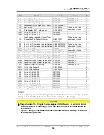
Parts listed in Table 5-5, we recommend to be replaced on the occasion of each compressor overhaul.
When ordering parts, be sure to inform the (a) model name, (b) serial number, (c) part name, (d) code
No. and (e) quantity required, to our sales offices or service centers.
In particular, if the serial number (b) is unknown, the details of the applicable design and manufacturing
specifications cannot be identified, and thus it becomes difficult to choose correct parts. So, make sure
to inform the (b) serial number to us.
Table 5-5 Replacement Parts of 3225**C Overhauling
P/N
Part Name
Code No.
Remarks
Q’ty.
6-1
Gasket, Suction Cover (1)
CS00600-4032CN
1
6-2
Gasket, Suction Cover (2)
CS00600-320N
1


