


13
Appendix
64
V2.20161017
30252060-02-EN
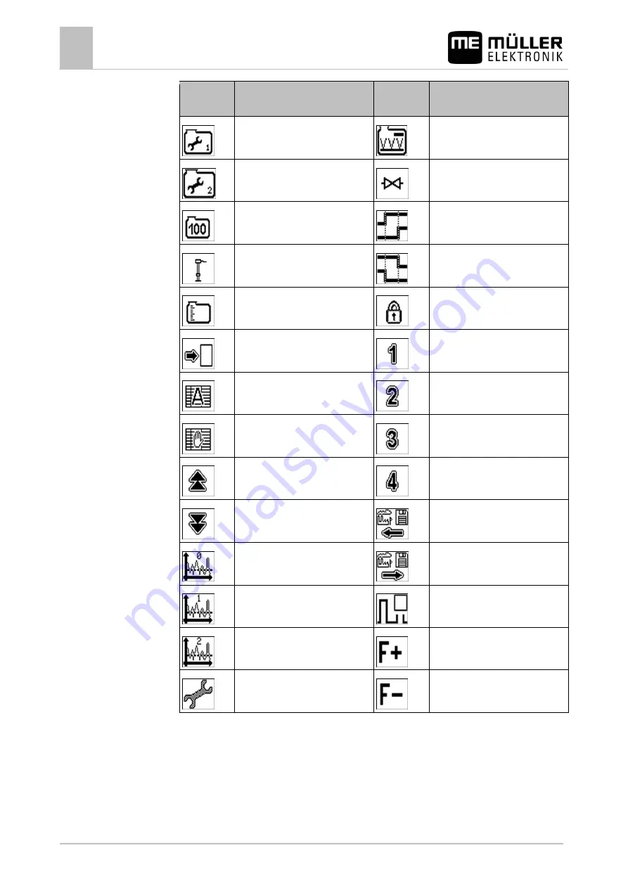
Function
icon
Function
Function
icon
Function
Carry out 100 litre calibration [
Carry out basic initialisation [
Calibrate tank or select tank type [
Open locked area
Enter a figure in the protected
area
Enter a figure in the protected
area
Enter calibration values manually [
Enter a figure in the protected
area
Scroll up through measured
values
Enter a figure in the protected
area
Scroll down through measured
values
Set sensor sensitivity to high [
Set sensor sensitivity to normal [
Set sensor sensitivity to low [
View configuration of external
devices [
Summary of Contents for TANK-Control II
Page 65: ...w w w R O L T R O N I K p l...
Page 66: ...w w w R O L T R O N I K p l...


