


Temposonics
®
R-Series
V
PROFINET IO RT & IRT
Operation Manual
I 24 I
6. Programming and configuration in the TIA Portal
6.1 General Information
This instruction describes as an example the integration and
programming of a Temposonics
®
R-Series
V
sensor with PROFINET
into the TIA Portal (Totally Integrated Automation Portal) of
Siemens AG. For controllers and software of other versions and
manufacturers, the operation may differ.
After you have created a project, you can include the sensor via its
GSDML file. The properties and functions of a PROFINET IO field
device are described in a GSDML (General Station Description) file.
The XML-based GSDML file contains all relevant data that is important
for both the implementation of the device in the controller and the data
exchange during operation.
The GSDML file for the R-Series
V
PROFINET is available on our
homepage
www.mtssensors.com
. The GSDML file of the R-Series
V
PROFINET is packed into a zip file containing the data for the MTS
profile and encoder profile.
Download the GSDML file and save it on your computer. To include
the GSDML file, select "Tools" from the menu bar of the TIA portal
and click on "Manage device description file (GSD)". The "Manage
device description files" window opens (Fig. 311). Enter the source
path where the R-Series
V
PROFINET with MTS profile GSDML file is
stored. Specify the location and press the "Install" button to install the
GSDML file. The default name of the R-Series
V
PROFINET sensor is
"MTS-R-Series-PNIO-MIF". This name can be changed.
Fig. 31: The installed GSDML files
6.2 Parameter description for MTS profile
5.3 Supported network functions
Following network functions are supported:
• RTC (Class 1 & Class 3) (Real Time Cyclic Protocol):
Protocol for cyclic IO data (process data and measured values)
• RTA (Real Time Acyclic Protocol):
Protocol for acyclic real time data (e.g. alarms)
• DCP (Discover and Basic Configuration Protocol):
Assignment of IP configuration and device name
• DCE/RPC (Distributed Computing Environment Remote Procedure Call):
Remote Procedure Calls via IP (e.g. parameter configuration)
• LLDP (Link Layer Discovery Protocol):
Protocol used for neighborhood detection
• SNMP (Simple Network Management Protocol):
Protocol used for network node diagnosis
• MRP (Media Redundancy Protocol):
Searches for alternative routes in case of cable error or node error
Supported network Topologies
PROFINET supports various topologies when building up a network.
Thus, the usage of linear, star, ring and tree topologies are supported.
For these topologies, switches are integrated in devices like the
R-Series
V
PROFINET sensors. With integrated switches, a power
failure will cause a communication interruption to the subsequent
devices. This can be avoided, for example, by extending the line
structure to a ring structure.
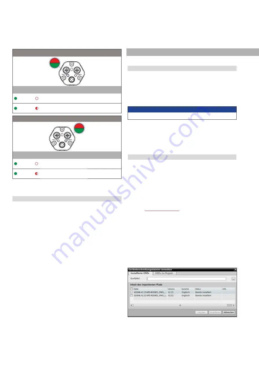
ort
1
4
5
2
1
4
5
2
S E
S
r
n
d
,QIRUPDWLRQ
ON
OFF
Connection to the next network node
established
ON
Flashing
Connection to the next network device
established & communication active
ort
1
4
5
2
1
4
5
2
S E
S
r
n
d
,QIRUPDWLRQ
ON
OFF
Connection to the next network node
established
ON
Flashing
Connection to the next network device
established & communication active
Fig. 30: LED status, part 2
NOTICE
Follow the information given in the controller operation manual.
Chapter 6.2 contains the integration and programming of the
R-Series
V
PROFINET with MTS profile (U402/U412). The
implementation and configuration of the R-Series
V
with encoder
profile (U401/U411) is described in chapter 6.3.


