English
Operating manual for snow thrower
10
Maintenance tasks
`~ìíáçå
mçëëáÄáäáíó=çÑ=ÇçáåÖ=Ç~ã~ÖÉ=
íç=íÜÉ=ã~ÅÜáåÉ
tÜÉå=êÉéä~ÅáåÖ=é~êíë=çÑ=íÜÉ=ã~ÅÜáåÉ=
ìëÉ=çåäó=çêáÖáå~ä=ëé~êÉ=é~êíëK
`~ìíáçå
båÖáåÉ=çáä=áë=Ü~ò~êÇçìë=
íç=íÜÉ=ÉåîáêçåãÉåí
^ÑíÉê=ÅÜ~åÖáåÖ=íÜÉ=çáäI=í~âÉ=íÜÉ=
ï~ëíÉ=çáä=íç=~=ï~ëíÉ=çáä=ÅçääÉÅíáåÖ=
éçáåí=çê=íç=~=ï~ëíÉ=Çáëéçë~ä=
Åçãé~åóK
Clean the machine
^ííÉåíáçå
aç=åçí=ÅäÉ~å=íÜÉ=ìåáí=ïáíÜ=~=ÜáÖÜJ
éêÉëëìêÉ=ÅäÉ~åÉê
Park the machine on a firm, even
and horizontal piece of ground.
Remove any dirt sticking to it.
Clean the machine by pouring
water through the throw-out
chute, leave it to dry.
Clean engine with a cloth and
brush.
Lubrication
Lubricate all rotating and mobile
parts with a light oil.
Adjust tyre pressure
^ííÉåíáçå
oáëâ=çÑ=Éñéäçëáçå>
kÉîÉê=ÉñÅÉÉÇ=íÜÉ=ã~ñáãìã=íóêÉ=
éêÉëëìêÉ=çÑ=NKQ=Ä~êLOM=éëáK
Recommended tyre pressure:
1.0 bar.
Checking and setting
the worm drive clutch
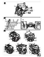
Fig. 2A
Release clutch lever (1).
There must be no slackness
on the coupling cable (2) but
it must not be taut either.
Adjust if necessary (see “Making
adjustments to the coupling
cable”).
It must be possible to depress
the clutch lever (1) all the way.
If it does not, the coupling cable
is tightened too firmly and must
be slackened (see “Making adjust-
ments to the coupling cable”).
Additional check: (see “Working with
the unit/ operating sequence”)
When the motor is running
(“
”), switch on the auger drive
for 10 seconds.
Release the clutch lever, the
snow-throwing auger must
no longer rotate.
Check and set clutch
for travel drive
Fig. 1
(Machines with caterpillar drive)
Set setting lever (Fig. 4, Pos. 1)
to position IV (Transport).
Set shift lever (6) to the fastest
forward gear (highest figure).
Having released the coupling lever (2),
push the machine forwards.
While pushing, move the shift
lever (6) to fastest reverse gear
“R
/R2” and then to fastest
forward gear.
If some resistance is felt while
you are pushing the machine
or changing gear, you need
to slacken the coupling cable
(see “Making adjustments to the
coupling cable”).
While you are pushing the machine,
press coupling lever (2).
The wheels/caterpillar tracks must
become blocked. If not, tighten the
coupling cable a little (see “Making
adjustments to the coupling cable”).
If the setting is still not correct,
repeat the process.
Making adjustments
to the coupling cable
Fig. 2B
For clutch cables with adjusting
plate for wheel drive (3) or for
worm drive (4):
– Tension: Loosen screw (A) depen-
ding on the adjusting plate, push
down adjusting plate and retigh-
ten screw (A).
– Slacken: Loosen screw (A) depen-
ding on adjusting plate, push
up adjusting plate and retighten
screw (A).
Adjust shift lever
Units with shift linkage (1)
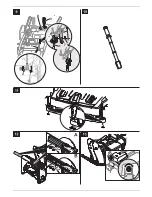
Fig. 9
Remove spring clip (4) and washer
(5), extract spindle nut (6) from
the hole (7).
Press gearshift arm (2) downwards,
set shift lever (3) to gear “6”.
Rotate spindle nut (6) in such
a way that the pin can be put
into the same hole (7).
Secure spindle nut with washer
and spring clip.
Note
This setting is not required unless
the quickest gear (forwards or
backwards) cannot be engaged.
Adjusting the caterpillar
track (Machines with
caterpillar drive)
Note
Have this work carried out only
by a specialist workshop.
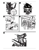
Fig. 5
The caterpillar track (1) has been set
correctly when it can be depressed
manually by 9–10 mm (applying
a pressure of 6.4–9 kg).
If it can be forced down by a greater
or lesser amount, it must be
adjusted:
Position unit on a secure and level
surface.
Loosen nut (3) on each caterpillar
side.
Rotate nut (2) until the caterpillar
track has the correct tension:
– To tighten, rotate in clockwise
direction.
– To slacken, rotate in anti-
clockwise direction.
Retighten nut (3) on each cater-
pillar side.
Note
Adjust both caterpillar tracks evenly
so that the rear axle (4) is parallel to
the front axle. In doing so, the length
of the thread (x) on both adjusting
screws should be the same.
Summary of Contents for Cub Cadet E 22
Page 1: ...769 20912B MTD Products Aktiengesellschaft Saarbrücken Germany E 22 ...
Page 2: ......
Page 3: ...E D C A B A B 1 2 A A ...
Page 4: ...9 10mm max ...
Page 5: ...3 8 2 6 1 7 5 4 1 ...
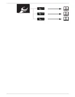
Page 6: ...Typ 1 Typ 2 Typ 3 109 111 113 ...
Page 7: ...4 13 24 34 44 54 63 72 81 90 99 ...
Page 113: ...1 66 Typ 5 Typ 1 109 ...
Page 114: ...A B Typ 5 Typ 1 110 ...
Page 115: ...1 66 Typ 5 Typ 2 111 ...
Page 116: ...A B Typ 5 Typ 2 112 ...
Page 117: ...1 66 Typ 3 113 ...
Page 118: ...A B Typ 5 Typ 3 114 ...


