


4.5
Fluid Pumping Connections and Pressure Relief Considerations
When determining the design of the pump installation, clearance is recommended for inlet and outlet
connections as well as providing for a pressure relief device for the discharge line.
A pressure relief device is
required for all applications of this pump.
Failure to implement a pressure relieving device may result in
significant damage to the pump and attached piping, serious injury or death of personnel, and will void
the pump warranty.
Please read the following concerning pressure relief devices and the allowable mounting
locations.
Spring loaded ball and seat relief valves:
Pressure relief devices of this type rely on a ball and seat interface to create a seal. Force is exerted on the ball,
typically with springs, to balance a pre-determined line pressure. This type of pressure relief device is not
designed for full opening once relief pressure has been achieved, in other words,
a ball and seat relief valve is
not a full volume relief device and if sufficient fluid volume is present may cause line pressure to continue
to rise due to the small flow area available
. As the line pressure exceeds the set pressure of the relief valve,
the ball temporarily separates from the seat thus allowing excess pressure to flow through. Once line pressure
has dropped below the set pressure of the relief valve, the ball will re-seat. Due to the small volume relief
capacity these types of pressure relief devices it is acceptable to install them on a fluid end gauge connection(s).
While not intended as a full-bore volume relief device connection point, the gauge connection will provide a
sufficient conduit for a ball and seat type relief valve.
Valves or other closure devices shall not be installed
between the pop-off valve and the fluid end.
Always follow the manufacturer’s recommendations for the
installation, use, and maintenance of the relief valve.
Full bore (pop-off) relief valves:
Full-bore relief valves are designed to allow full bore dissipation of pressure by relieving large volumes of fluid.
As such,
these relief devices must not be installed on the fluid end gauge connection(s).
The pop-off valve
should be installed as close to the fluid end as possible and in the discharge piping circuit at either the blind side
of the fluid end (for single side discharge) or connected to a TEE fitting on the discharge side of the fluid end.
Valves or other closure devices shall not be installed between the pop-off valve and the fluid end.
Always
follow the manufacturer’s recommendations for the installation, use, and maintenance of the pop-off valve.
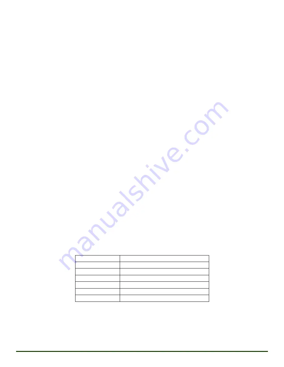
Below are the maximum relief set pressures based on plunger diameter.
Plunger Diameter Relief Device Maximum Set Pressure
2.75”
15,000 psig
3.00”
15,000 psig
3.25”
11,020 psig
3.50”
11,020 psig
4.00”
8,438 psig
4.50”
6,667 psig
See drawing on following page for piping location dimensions and pressure relief mounting locations.
Revision K 03/12/2019
MSI - A Division of Dixie Iron Works, Ltd. All rights reserved.
Page 25