MM64003a_e.doc / Feb-09
Page 4 / 44
1.
Introduction and Application
The MM640 motion monitor has been designed for monitoring and control of admissible and
impermissible operating conditions on machinery systems like conveyors, hoisting devices and
many more. This unit is not just a speed monitor, but provides comparison between peripheral
motion, motor motion and scheduled demand values of the control system. The unit is designed
to generate OK signals or alarms upon programmable peripheral conditions. It provides four
relay outputs and four transistor outputs.
6 logical inputs can pick up remote commands or peripheral states, and this information can be
included into the combination of events for setting or resetting alarms.
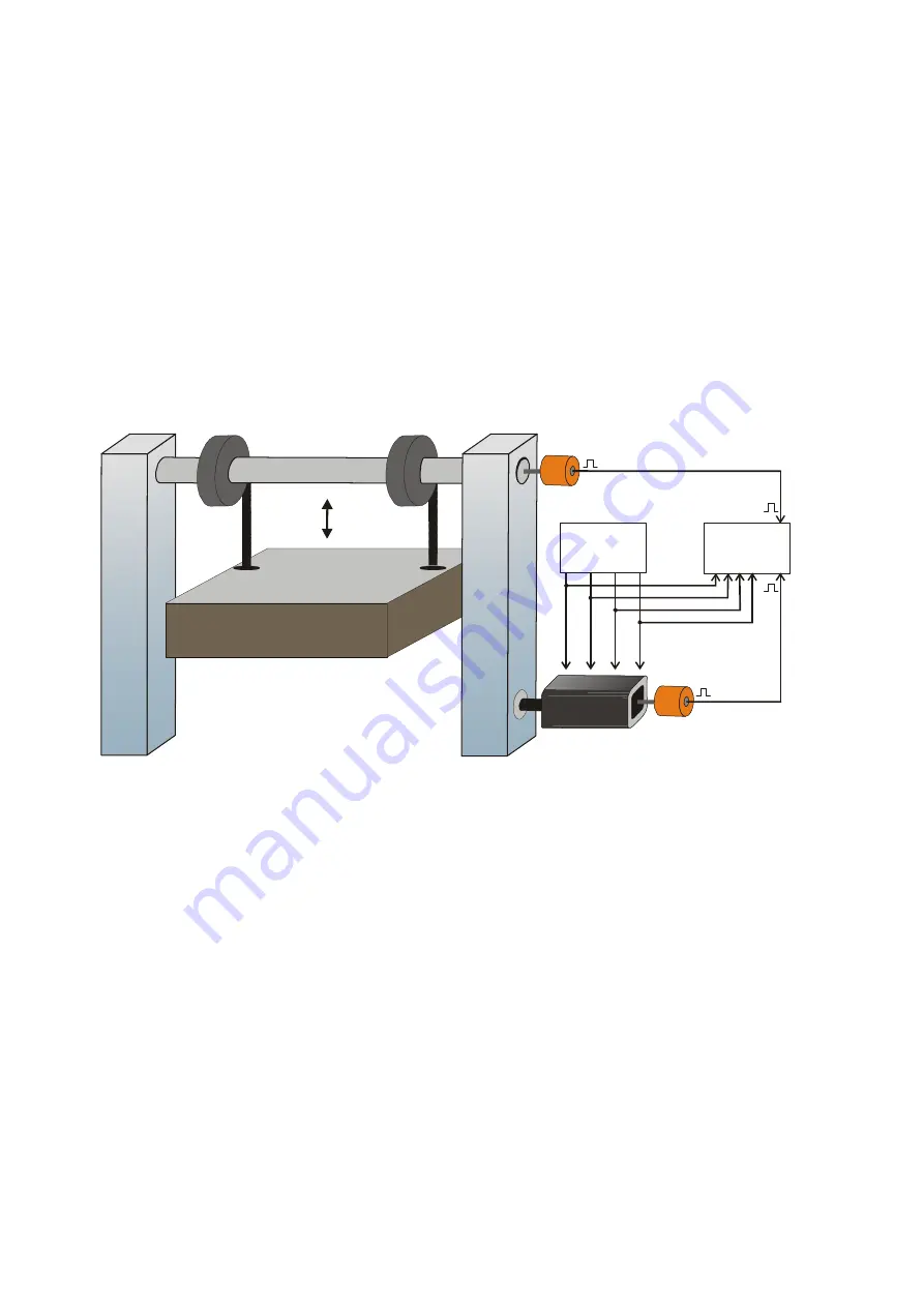
The example below shows a hoisting unit where a motor moves the load up and down, via
gearbox or other mechanical transmission.
U
P
D
O
W
N
F
a
st
s
p
ee
d
B
re
ak
Control System
MM 640
Motor
G
e
a
rb
o
x
Encoder 1
Encoder 2
In a situation like shown the MM640 unit could e.g. provide the following alarms:
a)
The motor is in standstill, but the load is still moving (gearbox problem)
b)
The speed command is “UP” but the load does not move at all or even moves into
the wrong direction
c)
No speed command is applied and the break is engaged, but still the motor or the load
are moving (break problem)
d)
The command is “Slow Speed Down” but the actual speed of the load exceeds the
permissible “Slow Speed” limit
e)
the displacement of the load indicated by encoder 2 does not match up with the number
of pulses generated by encoder 1, with consideration of the gearbox ratio (slip problem)
Furthermore the MM640 can take over limit switch functions for the permissible upper and
lower positions of the load etc. All desired functions can be easily configured by PC, just by
clicking a few checkboxes in a “logical AND / OR” matrix on the screen.
Summary of Contents for MM 640
Page 15: ...MM64003a_e doc Feb 09 Page 15 44...


