Fs340_02b_oi_e.docx / Nov-21
Page 45 / 49
•
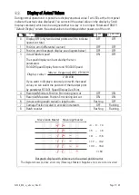
If during forward acceleration the position error takes high positive values and the bar
graph moves to the extreme right position, this indicates that the carriage drive cannot
follow the acceleration ramp and you should decrease the “Acceleration 1” setting. The
same is valid for “Acceleration 2”, when during reverse acceleration you observe high
negative errors and the bar graph moves to the extreme left.
•
Where you find your position error remains small enough all the time, you are free to
increase the Acceleration settings. This will cause steeper ramps and therefore increase
your total cutting output.
All this assumes that you have properl
y adjusted your analogue output by parameter “Gain
Total” in a way that the bar graph remains in centre position when the carriage moves at
constant speed.
Remark: Position errors will not affect the cutting accuracy, unless they occur directly during
the cut and are different with each cut.
At this time you can try to optimize also other settings:
•
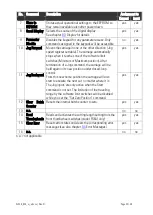
Using and Adjusting the Integrator:
When, for stability reasons, you needed to keep your ” Gain Correction” value low, any
important non linearity in your drive system could cause remaining position errors during
the synchronous phase. In this case set “Integration Time” to 100 …10 or even lower. The
Integrator will reduce the position error always into a +/-6 increments error window. The
lower the Integration Time setting, the faster it will catch up with the correct position. Too
low settings (= too high integration speeds) will however result in oscillation problems.
Wherever your differential counter remains in an acceptable range around zero (e.g. -
8 …
+8),
there is no need to use the integrator and you should leave ”Integration Time” set to 0.
•
Adjusting the Correction Divider:
Where you find the bar graph oscillates quickly around zero over several fields during the
synchronous phase, this indicates your encoder resolution is too high with respect to
mechanical clearance, backlash of tooth belts or other tolerances. To eliminate this, set
Correction Divider to 1 or 2 or higher until you observe more stable operation.
•
Increase the setting of “Return Speed”
to save time with the fly back of the carriage. If
necessary, the carriage then will take higher return speed, which increases again the total
cutting output.
•
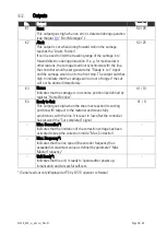
Increase the “Acceleration” settings as far as more dynamic motion is desirable and the
drive can follow.
•
Keep the cutting time (penetration time of the tool or saw blade) as short as possible to
achieve maximum efficiency
This concludes the procedure of commissioning of your Flying shear system. We recommend
saving all parameter settings. In case of repeat applications (machine with similar
specifications), or after exchange of the controller, you just need to download the settings and
are immediately ready to go.


