Fs340_02b_oi_e.docx / Nov-21
Page 13 / 49
Control Inputs Cont.1
–
Cont.4
These inputs can be configured for remote functions like Reset, Start, Cut completed,
Immediate cut or display selection purpose.
All control inputs require HTL level. They can be individually set to either NPN (switch to -) or
PNP (switch to +) characteristics. For applications where edge-triggered action is needed, the
menu allows to set the active edge (rising or falling). The Control inputs will also accept signals
with Namur (2-wire) standard.
For reliable operation of the Control Inputs a minimum impulse duration of
50 µsec. must be ensured. Especially when using the Z marker pulse of a
HTL encoder for index tracking, please verify that this minimum duration can
be kept even with maximum speed of the machine
Switching Outputs K1
–
K4
FS340 provides four digital outputs to signal control states like Ready to Cut, Alarm or Error. K1
–
K4 are fast-switching and short-circuit-proof transistor outputs with a switching capability of
5
–
30 volts / 350 mA each. The switching voltage of the outputs must be applied remotely to
the Com+ input (terminal 29).
Serial Interface
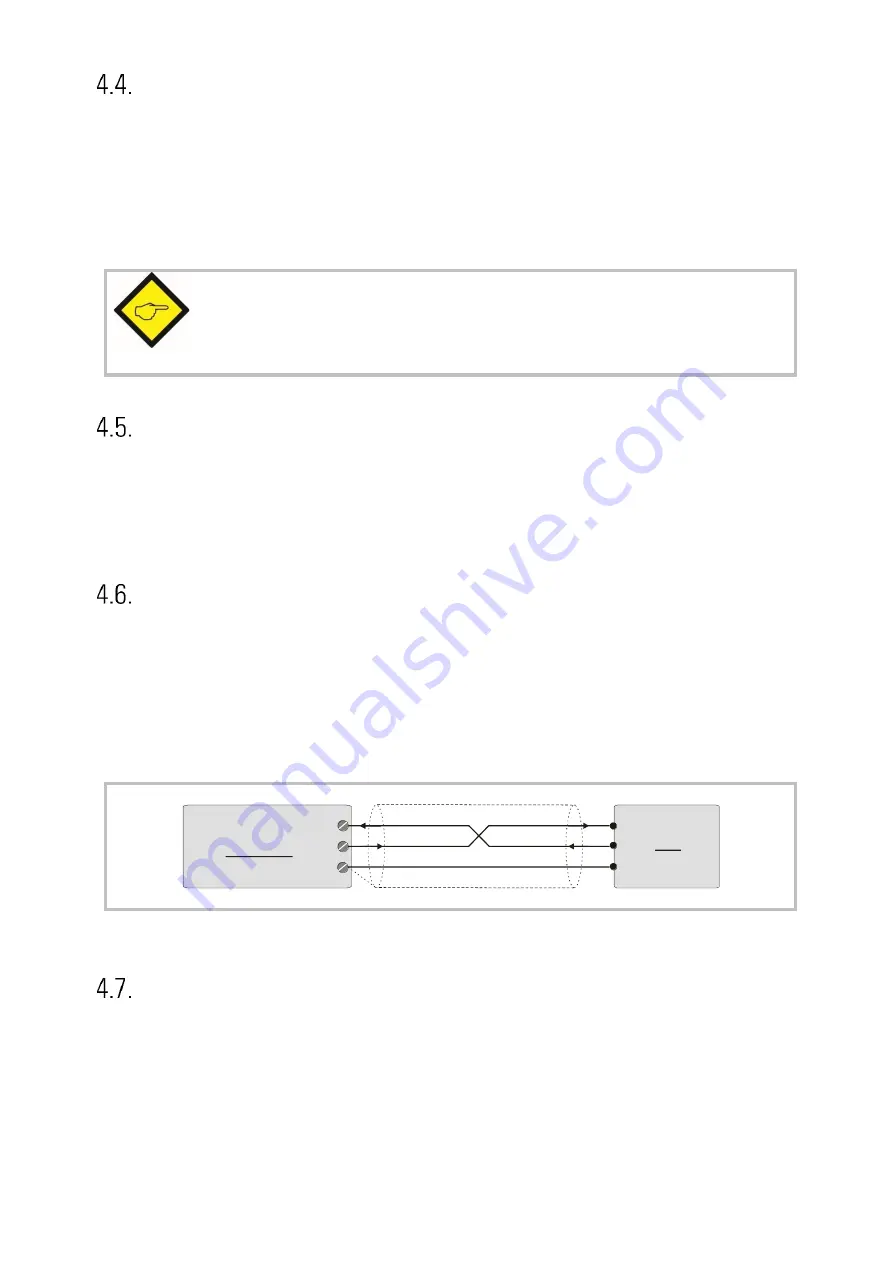
The serial RS232 interface can be used for the following purposes:
•
Set-up of the unit by PC with use of the OS10 PC software
•
Remote change of parameters during operation
•
Remote readout of actual values by PLC or PC
The figure below explains the connection between the FS340 unit and a PC using the standard
Sub-D-9 serial connector
2
3
5
RxD
TxD
GND
screen
PC
FS 340
14
(Sub-D-9)
30
31
TxD
RxD
For details of the serial communication protocol, please refer to the special “Serpro” manual.
Analogue Outputs
The unit provides a voltage output of +/- 10 volts (load = 3 mA), and a current output of
0
–
20 mA (load = 0
–
270 Ohms), both at a resolution of 14 bits (13 bits + sign).
With most standard applications the voltage output is used as a speed reference signal,
connected to the speed input of the carriage drive.


