Fs340_02b_oi_e.docx / Nov-21
Page 23 / 49
F02
Range
Default
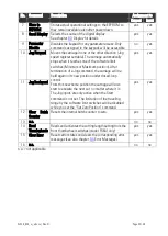
F02.006 Integration Time:
Time constant for the phase integrator, which avoids
positional errors. To be entered as number of cycles (1 cycle
= 250 µsec) per increment
0 … 9999
0000 =
Integrator off
0001 = fast
9999 = slow
500
F02.007 Correction Divider:
Function to provide a digital attenuation of the phase
correction signal that is produced, when the drive on
mechanical grounds (dead band or backlash) cannot respond.
In such a case, it is not desirable to make corrections
immediately. The "Correction Divider" provides a window for
the drive "backlash", within which the controller produces no
correction and a division of the differential error count.
0 = No window, Reaction to 1 increment, no division
1 = /- 1 increments, error division by 2
2 = /- 2 increments, error division by 4
3 = /- 4 increments, error division by 8
etc.
0 … 9
0
F02.008 Ramp Form:
Selects the shape of the ramps of the carriage speed profile.
Two types of ramps are available: linear and S-shaped
ramps. The selection can be made independently for each of
the four ramps of the speed profile by setting the
corresponding bit of the parameter “Ramp Form” either to 0
or to 1:
Bit 0: forward acceleration ramp
Bit 1: forward deceleration ramp
Bit 2: backward acceleration ramp
Bit 3: backward deceleration ramp
A ramp is S-shaped when the corresponding bit is 0 and it is
linear when the corresponding bit is 1.
Example:
Ramp Form = 00 means that all ramps are S-shaped, Ramp
Form = 01 means that only the forward acceleration ramp is
linear, and Ramp Form = 15 means that all ramps are linear.
0 … 15
0
S-shaped ramps are recommended when using drives with high response (e.g. servo
drives) whereas linear ramps are recommended for drives with lower response (e.g.
big DC drives).


