background image

Fs340_02b_oi_e.docx / Nov-21 


Page 32 / 49 


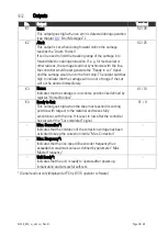
Unconnected NPN inputs are always HIGH (internal pull-up resistor) 


Unconnected PNP inputs are always LOW (internal pull-down resistor) 


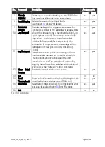
Serial Communication Parameters 

F07 


Range 

Default 

F07.058  Serial device address (unit number) 

11 … 99


11 

F07.059  Serial baud rate 

0 … 6


0=    9600 Baud 


1=    4800 Baud 


2=    2400 Baud 


3=    1200 Baud 


4=      600 Baud 


5=  19200 Baud 


6=  38400 Baud 


F07.060  Serial data format 

0 … 9


0=  7 Data, Parity even, 1 Stop 


1=  7 Data, Parity even, 2 Stop 


2=  7 Data, Parity odd,   1 Stop 


3=  7 Data, Parity odd,   2 Stop 


4=  7 Data, no Parity,  1 Stop 


5=  7 Data, no Parity,  2 Stop 


6=  8 Data, Parity even, 1 Stop 


7=  8 Data, Parity odd,   1 Stop 


8=  8 Data, no Parity,  1 Stop 


9=  8 Data, no Parity,  2 Stop 


Summary of Contents for FS340

Page 1: ...mooth motion by optimized S shape profiles High dynamic response by means of short cycle time therefore accurate cutting results also during change of line speed Most compact unit including operator panel for direct access and RS232 interface for remote access Analog output configurable for voltage or current operation PROFIBUS DP interface available option 24 VAC 17 40 VDC power supply Available ...

Page 2: ...le at https www motrona com en support software html Version Description FS34001a June 12 TJ First edition FS34002a March 15 TJ New parameter F03 029 031 new master speed display Fs340_02b_oi Sep 21 TJ Setup with PC Software OS10 Legal notices All contents included in this manual are protected by the terms of use and copyrights of motrona GmbH Any reproduction modification usage or publication in ...

Page 3: ... Normal Operation 16 General Setup Procedure 16 Direct Fast Access to Cutting Length Setting 17 Change of Parameter Values on the Numeric Level 18 Code Protection against Unauthorized Keypad Access 19 Return from the Programming Levels and Time Out Function 19 Reset all Parameters to Factory Default Values 19 Summary of the Menu 20 Descripotion of the Parameters 22 Length Setting 22 Operational Se...

Page 4: ...rror Messages 38 Download of the Adjust Program 40 Use of the Adjust Program 41 Set Directions of Rotation 42 Set Directions of Rotation without PC 43 Tuning the Analogue Output 43 Setting of the Proportional Gain 44 Tuning the Controller 44 Relay Outputs 46 Front Thumbwheel Switches 46 Model FS340 48 Model FS641 49 ...

Page 5: ...e right to modify the hardware software or operation manual at any time and without prior notice Therefore there might be minor differences between the unit and the descriptions in operation manual The raiser respectively positioner is exclusively responsible for the safety of the system and equipment where the unit will be integrated During installation or maintenance all general and also all cou...

Page 6: ...indicated as separator Incoming as well as outgoing wires and wires for extra low voltages ELV must be separated from dangerous electrical cables SELV circuits by using a double resp increased isolation All selected wires and isolations must be conformed to the provided voltage and temperature ranges Further all country and application specific standards which are relevant for structure form and q...

Page 7: ... be mounted in a metal enclosure with sufficient distance to sources of electromagnetic noise Run signal and control cables apart from power lines and other cables emitting electromagnetic noise Please also refer to motrona manual General Rules for Cabling Grounding Cabinet Assembly You can download that manual by the link https www motrona com en support general certificates html Cleaning Mainten...

Page 8: ...bits 4 power transistor outputs alert FS641 Front size 96 x 96 mm 3 780 x 3 780 Cutting length setting by keypad or by front thumbwheel switches Analogue output 14 bits 4 power transistor outputs alert and 4 relay outputs alert Both models are suitable for front panel or operator desk mounting by means of the included mounting clamps Where you desire to mount the units on DIN rails inside a cabine...

Page 9: ...t performance under all operating conditions This unit is very easy to set up All settings can be made either by keypad and display at the unit or by PC with use of the motrona operator software OS10 All relevant operational parameters and variables are accessible by RS232 RS485 interface For PROFIBUS applications our PB251 gateway is available Therefore the user has multiple possibilities for rem...

Page 10: ...Cont 3 Com K1 K4 TxD RS232 Ana out 10V Ana out 20 mA RxD RS232 PROG X1 X2 5 A A B B 5 A A B B Cont1 Cont2 Cont3 Cont4 Reset Start Immediate Cut Cut completed etc RxD TxD GND RS232 24 V DC Power supply Com K1 K4 K1 out K2 out K3 out K4 out 24 24 10V 20 mA 0V GND PROG 18 24 23 20 19 22 21 11 12 6 5 27 28 30 3 31 17 1 4 29 26 25 7 8 32 2 16 15 14 13 10 9 24 V AC Example shows wiring for encoders with...

Page 11: ...10V Analogue output 10V 0 10V Slave speed reference 17 Vin Power supply input 17 40 VDC or 24 VAC 18 5 2V out Aux output 5 2V 150 mA for encoder supply 19 24V out Aux output 24V 120 mA for encoder supply 20 GND Common Ground Potential 0V 21 Slave B Carriage encoder channel B non inverted 22 Slave A Carriage encoder channel A non inverted 23 Master B Line encoder channel B non inverted 24 Master A ...

Page 12: ...ial with inverted signal TTL inputs at a level of 3 0 to 5 volts single ended HTL signals at a 10 30 volts level alternatively differential A A B B or single ended A B only Impulses from photocells or proximity switches etc providing a HTL level 10 30 volts Proximity switches according to NAMUR 2 wire standard may need additional remote resistor requires special settings of the threshold parameter...

Page 13: ...s like Ready to Cut Alarm or Error K1 K4 are fast switching and short circuit proof transistor outputs with a switching capability of 5 30 volts 350 mA each The switching voltage of the outputs must be applied remotely to the Com input terminal 29 Serial Interface The serial RS232 interface can be used for the following purposes Set up of the unit by PC with use of the OS10 PC software Remote chan...

Page 14: ...ll start the cutting procedure while the carriage will exactly follow the material When the cut is done a remote Cut completed signal must tell the controller to decelerate and then return the carriage back to the home position again All speed transitions use self optimizing S shape profiles for minimum wear and tear of all mechanical parts unless a linear ramp form has specifically been selected ...

Page 15: ...yond 1 16 and 16 1 are not allowed Where applicable the x1 x2 or x4 hardware multiplication of the Master channel or the Slave channel may be used to adapt the frequencies The line encoder must be connected to input Master and the carriage encoder to input Slave For speed reference of the carriage drive the analogue output is used At any time the controller needs a remote signal upon completion of...

Page 16: ...d definition menu F06 e g Display scroll Immediate Cut or else General Setup Procedure The unit changes over from normal operation to setup level when keeping the key down for at least 2 seconds Thereafter you can select one of the parameter groups F01 to F09 Setup operation is disabled while the carriage is within a cutting cycle I e the setup procedure cannot be started before the Start command ...

Page 17: ...oups Actual Error Return to normal operation 10 Normal operation During the general setup procedure all control activities remain disabled New parameter settings become active after return to normal operation only Direct Fast Access to Cutting Length Setting To get to the fast access routine please press both and at the same time This will access the parameter group F01 right away To change the cu...

Page 18: ...d then shows negative and 1 minus one The example below shows how to change a parameter from the actual setting of 1024 to the new setting of 250 000 This example assumes that you have already selected the parameter group and the parameter number and that you actually read the parameter value in the display Highlighted digits appear on colored background Step Display Key action Comment 00 001024 D...

Page 19: ...ction At any time the PROG key sets the menu one level up and finally returns to normal operation The same step occurs automatically via the time out function when during a period of 10 seconds no key has been touched Termination of the menu by automatic time out will not store new settings unless they have already been stored by the PROG key after editing Reset all Parameters to Factory Default V...

Page 20: ...g Direction 002 Pulses Line 1000 029 Speed Display Factor 003 Pulses Cut 1000 030 Speed Display Divider 004 Acceleration 1 031 Speed Display Dec Point 005 Acceleration 2 F04 Definitions for the Slave Encoder 006 Integration Time 032 Encoder Properties 007 Correction Divider 033 Edge Counting 008 Ramp Form 034 Counting Direction 009 Synchron Time 035 Reserved 01 Tool Width 036 Reserved 011 Sampling...

Page 21: ... Function 082 Reserved 057 Reserved 083 Reserved F07 Serial communication 084 Reserved 058 Unit Number 085 Reserved 059 Serial Baud Rate 086 Reserved 060 Serial Format 087 Reserved 061 Reserved 062 Reserved 063 Reserved F08 Special functions 064 Input Filter 065 Trigger Threshold 1 066 Trigger Threshold 2 067 Brightness 068 Frequency Control 069 Length Store Configuration 070 Display Time 071 Defa...

Page 22: ...s 1000 length units LU forward and set the proper number of pulses here 1 999999 1000 F02 004 Acceleration 1 Acceleration rate of the carriage during forward motion Scaled in Length units per second squared LU s 1 99999 5000 F02 005 Acceleration 2 Acceleration rate of the carriage during reverse motion Scaled in Length units per second squared LU s 1 99999 5000 The controller generates ramps of a ...

Page 23: ... Window 2 increments error division by 4 3 Window 4 increments error division by 8 etc 0 9 0 F02 008 Ramp Form Selects the shape of the ramps of the carriage speed profile Two types of ramps are available linear and S shaped ramps The selection can be made independently for each of the four ramps of the speed profile by setting the corresponding bit of the parameter Ramp Form either to 0 or to 1 B...

Page 24: ... High Low 1 9999 1 F02 010 Tool Width Width of the saw blade or cutting tool scaled in LU 0 999 0 F02 011 Sampling Time Sets the internal digital feed forward control with respect to dynamics and resolution Lower set values result in faster response but less accuracy of the feed forward signal Higher set values result in better accuracy but slower response with sudden speed changes Feed forward si...

Page 25: ... the carriage has reached a stable position within the cut window and does not leave the window again right after the ready to cut output has been switched on Sync Samples n means that during n consecutive control cycles the carriage must be inside the window before the ready to cut signal is switched on This function should only be used for systems with poor dynamic performance Please note that t...

Page 26: ...nd sets the unit to an Error state when touched during production The front Max Position switch however is out of operation Instead the Alarm position switch see next parameter is monitoring the forward carriage motion and sets an alarm output when touched during a cutting cycle 99999 0 0 999999 99999 999999 F02 021 Alarm Position Sets an alarm position scaled in length units for the forward motio...

Page 27: ...ic length operation scaled in master encoder pulses When command Start is set the material length counter is set to this value Afterwards the register Set length Counter is cleared to zero set value only used one time 0 999999 0 F02 023 Rel Return Speed Sets the ratio between the actual line speed and the maximum return speed For example setting 2 00 says that if necessary the return speed is perm...

Page 28: ...tion x2 2 Full quadrature edge evaluation x4 F03 028 Counting direction 0 1 0 0 Up when A leads B 1 Down when A leads B F03 029 Speed Display Factor Multiplication factor to calculate the speed display value from the master frequency see chapter 8 3 1 999999 1 F03 030 Speed Display Divider Divider to calculate the speed display value from the master frequency see chapter 8 3 1 999999 1 F03 031 Spe...

Page 29: ...039 Offset Correction Digital setting of analogue offset on correction signal 10 000 10 000 volts 0 000 F05 040 Gain Correction Digital setting of the proportional gain of the control loop Setting to 2 048 results in a response of 1 mV per error bit Recommended setting 0 500 5 000 Gain Correction 2048 x xxx volts per error bit 0 51 200 2 000 F05 041 Max Correction Limitation of the output voltage ...

Page 30: ... more details about these functions see chapter 8 1 5 n a 6 Set Zero position 7 Store to EEPROM 8 Scroll Display 9 n a 10 Jog forward 11 Jog backward 12 Clear Batch Counter 13 n a 14 Read front thumbwheels model FS 641 only 15 Clear Error 16 n a F06 047 Function assignment to key DOWN 0 16 0 See key UP F06 048 Function assignment to key ENTER 0 16 0 See key UP n a not applicable ...

Page 31: ... Zero position 7 Store to EEPROM 8 Scroll Display 9 Parameter Input Disable 10 Jog forward 11 Jog backward 12 Clear Batch Counter 13 n a 14 Read front thumbwheels model FS 641 only 15 Clear Error 16 n a F06 051 Switching characteristics of input Cont 2 See Cont 1 F06 049 F06 052 Function assignment to input Cont 2 See Cont 1 F06 050 F06 053 Switching characteristics of input Cont 3 See Cont 1 F06 ...

Page 32: ...dress unit number 11 99 11 F07 059 Serial baud rate 0 6 0 0 9600 Baud 1 4800 Baud 2 2400 Baud 3 1200 Baud 4 600 Baud 5 19200 Baud 6 38400 Baud F07 060 Serial data format 0 9 0 0 7 Data Parity even 1 Stop 1 7 Data Parity even 2 Stop 2 7 Data Parity odd 1 Stop 3 7 Data Parity odd 2 Stop 4 7 Data no Parity 1 Stop 5 7 Data no Parity 2 Stop 6 8 Data Parity even 1 Stop 7 8 Data Parity odd 1 Stop 8 8 Dat...

Page 33: ...ting length set by the Direct Fast Access menu see chapter 5 3 is stored to EEPROM for enduring use F08 070 Display Time Update time sec for display only 0 005 9 999 0 050 F08 071 Default Display Number of actual value displayed by the unit after power up see table in chapter 8 1 at description of Scroll Display command 0 8 0 Must be set to the default value 166 for any kind of input signals excep...

Page 34: ...performed when the material is in standstill or when Start command is reset yes yes 4 Cut completed This input must receive a signal when mechanically a cut has been fully completed With the rising edge of this signal the controller will start deceleration and reversal in order to put the carriage back to its rear home position With this signal missing the carriage will continue to follow the mate...

Page 35: ...r Maximum position After termination of a Jog command the carriage will be held again in its new position under closed loop control From this new home position the carriage will also start to execute the next cut no matter where it is The Jog inputs are only active when the Start command is not set The limitation of the traveling range by the software limit switches will be disabled while you set ...

Page 36: ... if the cut will not be aborted immediately X2 25 K3 Home Indicates that the carriage is in its home position like defined by register Home Window X1 10 K4 Ready to Cut This output goes high when the shear has reached its cutting position with respect to the material and moves fully synchronous with the line It is reset to low after the controller has received the Cut completed signal X1 9 Max Cor...

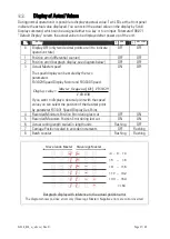
Page 37: ...FF OFF 3 Actual Master speed The speed display can be scaled by the two parameters F03 029 Speed Display Factor and F03 030 Speed 030 03 029 03 F F Hz frequency Master value Display If you want to display a decimal point with the speed value you can select the position of the decimal point by parameter F03 031 Speed Display Dec Point ON OFF 4 Recorded Minimum Position Error during last cut OFF ON ...

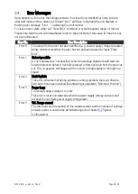
Page 38: ...r has not yet been cleared by input Clear Error Error 1 Cut not possible A cut is declared as not possible when the carriage already should start into forward direction before it has fully returned to Home position from the previous cut This in general will happen with too short cutting lengths at too high line speed Error 2 Limit Switch This error indicates that during automatic cutting operation...

Page 39: ...ine the encoder counting direction as described in chapter 9 4 Connect your PC to the controller as shown in chapter 4 6 and start the OS10 software The following screen will appear When you find the mask blank with the indication Unit Searching Unit at the top instead of the device version please click to the Com menu and check the serial settings of your PC A user manual of the OS10 you can find...

Page 40: ...ortional speed control only with the proportional Gain set as high as possible For the set up procedure it is recommended to mechanically disconnect the motor shaft from the carriage so you can run the motor continuously and need not to observe the mechanical limitations of the carriage Download of the Adjust Program The Adjust program is an external tool of the OS10 Before you can use it for the ...

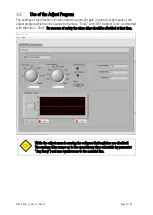
Page 41: ...ogram which can be opened in the menu Tools with OS10 Adjust Tools and started with the button Start For reasons of safety the slave drive should be disabled at that time While the adjust menu is running the software limit switches are disabled The carriage drive ramps up to line speed ramp time selectable by parameter Jog Ramp and runs synchronous to the material line ...

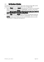
Page 42: ...ter value shown in the monitor window on the right It must count up to positive values and the frequency below must be positive Where you find it counts down and the frequency is negative please click to the switch Master Direction to change the counting direction Move the Slave encoder into forward direction manually or by enabling the Slave drive while the Master is moving forward Observe the Co...

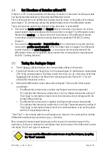
Page 43: ...ch Reset to ON by clicking to the corresponding softkey on the screen Enable both Master and Slave drive Turn the speed signal for the Master to approximate 25 of the maximum speed The Slave should now move too As a next step switch the Reset to OFF by clicking to the Reset button showing actually Reset On This will activate the closed loop control Observe the differential counter value and oscill...

Page 44: ... only To do this set parameter Sync Time to the desired synchronous time The carriage will then start the return cycle after lapse of this synchronous time regardless of the tool position Use the Jog function to put the carriage to the desired Home position Where your software limit switches should bar you from reaching the position keep input Set Zero Pos set during jog This will prevent limitati...

Page 45: ...e Integrator will reduce the position error always into a 6 increments error window The lower the Integration Time setting the faster it will catch up with the correct position Too low settings too high integration speeds will however result in oscillation problems Wherever your differential counter remains in an acceptable range around zero e g 8 8 there is no need to use the integrator and you s...

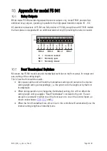
Page 46: ...en Normally closed Front Thumbwheel Switches Moreover the FS 641 models provide thumbwheel switches on the front panel for simple and easy setting of the cutting length This is how the front switches work Upon power up the unit will read the thumbwheel settings and overwrite the internal cutting length setting correspondingly i e the system cuts the length set by the front thumbwheels When during ...

Page 47: ...screw terminal 1 5 mm AWG 16 Control inputs Number of inputs Signal levels Characteristic Internal resistance Min pulse time Connections 4 configurable HTL LOW 0 2 5 V HIGH 10 30 V NPN PNP Namur Ri 3 3 kOhm 50 µs screw terminal 1 5 mm AWG 16 Control outputs Number of outputs Protection circuit Characteristic Output current Reaction time Connections 4 fast transistor outputs short circuit proof PNP...

Page 48: ...IP65 achievable SM300 optional mounting bracket for top hat rail mounting of FS340 units FS340 approx 250 g FS641 approx 370 g Ambient temperature Operation Storage 0 C 45 C 32 113 F not condensing 25 C 70 C 13 158 F not condensing Conformity standards EMC 2014 30 EU LV 2014 35 EU RoHS Ⅱ 2011 65 EU RoHS Ⅲ 2015 863 EN 61326 1 2013 for industrial location EN 55011 2016 A1 2017 A11 2020 Class A EN 61...

Page 49: ... 780 110 0 4 331 90 5 3 563 10 0 394 8 0 315 88 5 3 484 9 0 345 129 0 5 079 140 5 5 531 96 0 3 78 18 5 728 111 5 4 39 With optional plexi glass cover for protection class IP65 motrona part 64026 12 0 472 Panel cut out b x h 89 x 91 mm 3 504 wide x 3 583 high ...

Reviews: