Fs340_02b_oi_e.docx / Nov-21
Page 44 / 49
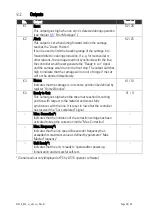
Setting of the Proportional Gain
The register “
Gain Correction
” determines how strong the controller responds to position and
speed errors of the drive. In principle, this setting therefore should be as high as possible.
However, depending on dynamics and inertia of the whole system, too high gain values will
produce stability problems.
Please try to increase the setting of Correction Gain from 0.500 to 1.000, 1500, 2.000, 2.500,
3.000 etc. However, as soon as you find unsteady operation, noise or oscillation, you must
reduce the setting again correspondingly.
We also recommend to ramp up and down the master while checking the differential counter
for stable operation.
Once you have successfully concluded these steps, you can exit the Adjust menu.
Now your machine is ready for operation and you can run initial test cuts without material (see
next chapter).
Tuning the Controller
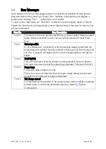
When during commissioning you cannot get the “Cut completed“ signal
because the carriage
drive is mechanically disconnected to the machine, it is legal to link the “Ready to cut” output
directly to the “Cut completed” input.
This however is allowed for testing purpose without material only!
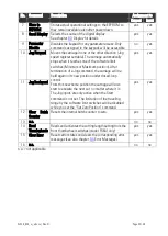
To do this, set parameter “Sync Time” to the desired synchronous time. The carriage will then
start the return cycle after lapse of this synchronous time, regardless of the tool position.
•
Use the Jog function to put the carriage to the desired Home position. Where your software
limit sw
itches should bar you from reaching the position, keep input “Set Zero Pos.” set
during jog. This will prevent limitation by the software switches because the counter for the
carriage position is kept to zero.
•
Make sure that
–
with respect to your definition of the zero position
–
your software limit
switches are set correctly, so that the carriage can move inside the designated traveling
range, but cannot leave it.
•
For the very first trials you should use a long length setting (“Cutting Length”) an
d a slow
line speed.
•
Start the line drive or move the measuring wheel at the line encoder to simulate the moving
material.
•
Set “Immediate Cut” command and see how the controller executes a first cutting cycle.
•
Set the “Start” command. The carriage will wai
t for expiration of the preset cutting length
and then execute a cutting cycle
•
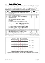
Observe the position error at the differential counter or the bar graph display. During the
whole cycle the position error should not exceed values like 30 and the bar graph should
remain in the centre area all the time. Increase the line speed step by step and continue the
observations.


