background image

6 - 18 WT4070/90 Wearable Terminal Integrator Guide

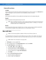
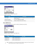
6.

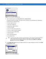
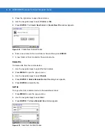
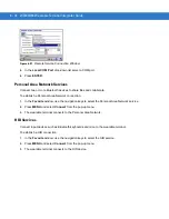
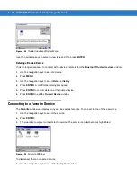
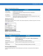
Use the arrow keys to select a device from the list and press 

ENTER

. The 

PIN Code Request

 window 

appears.

Figure 6-24    

Connection Favorite Options Window

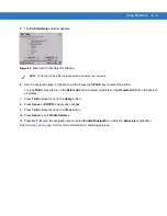
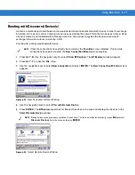
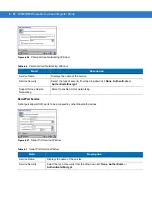
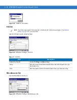
7.

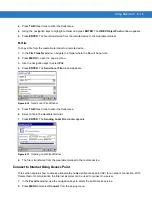
In the 

PIN Code

 field, enter the PIN code.

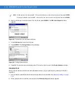
8.

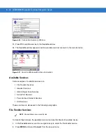
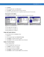
Press 

ENTER

. The 

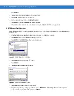
Pairing Status

 window displays.

Figure 6-25    

Pairing Status Window

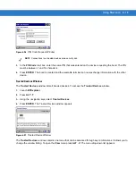
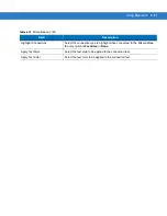
9.

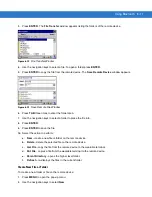
Press 

P2

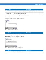
. The devices are successfully paired. The device name moves to the 

Trusted Devices

 window.

Accepting a Bond

When a remote device wants to bond with a wearable terminal, you give permission by entering a PIN when 
requested.

1.

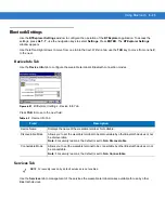
Ensure that the wearable terminal is set to discoverable and connectable. See 

Bluetooth Settings on page 

6-23

.

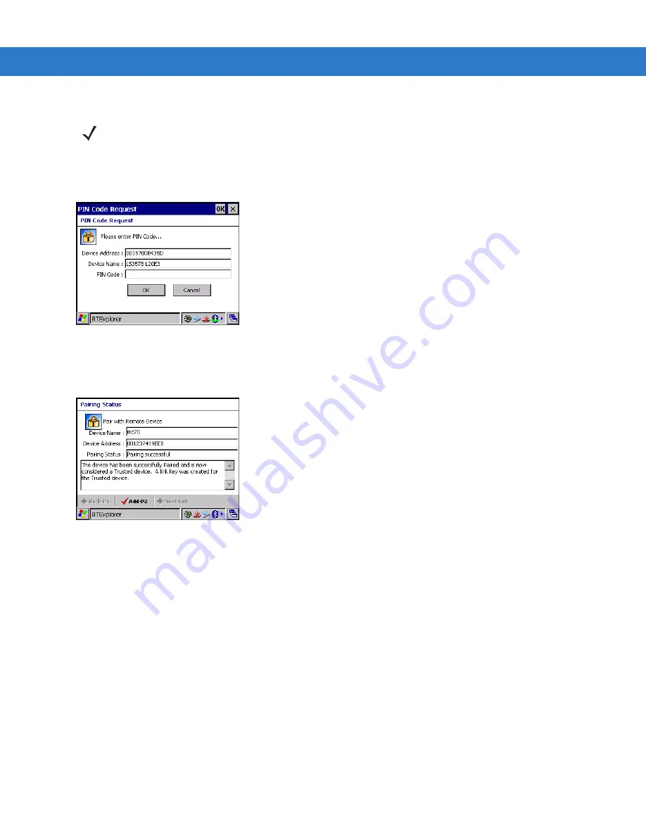
2.

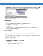
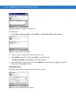
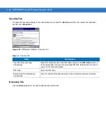
When prompted to bond with the remote device the 

PIN Code Request

 window appears.

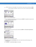
NOTE

To filter devices in the list press 

ALT

 - 

F

 to open the filter menu. Select a device type and then press 

ENTER

.

To change the display view press 

ALT

 - 

to open the view menu. Select a view type and then press 

ENTER

.

Summary of Contents for WT4090

Page 1: ...WT4070 90 Wearable Terminal Integrator Guide ...

Page 2: ......

Page 3: ...WT4070 90 Wearable Terminal Integrator Guide 72E 87638 07 Rev A April 2015 ...

Page 4: ...xcept as permitted under copyright law The user shall not modify merge or incorporate any form or portion of a licensed program with other program material create a derivative work from a licensed program or use a licensed program in a network without written permission from Zebra The user agrees to maintain Zebra s copyright notice on the licensed programs delivered hereunder and to include the s...

Page 5: ... Add 128 MB configuration wall mounting bracket Fusion 2 5 information 03 Rev A 05 06 08 Add BTExplorer support and freezer pouch information 04 Rev A 12 20 08 Add touch screen configuration 05 Rev A 03 03 09 Update Ethernet cradle daisychaining information 06 Rev A 12 15 09 Add Voice Only WT4090 information 07 Rev A 04 30 15 Zebra re branding ...

Page 6: ...iv WT4070 90 Wearable Terminal Integrator Guide ...

Page 7: ...d 1 4 Installing and Removing the Main Battery 1 4 Installing the Main Battery 1 4 Charging the Battery 1 5 Charging the Main Battery and Memory Backup Battery 1 5 Charging Spare Batteries 1 6 Removing the Main Battery 1 6 Starting the Wearable Terminal 1 7 WT4070 90 Boot Up 1 7 Voice Only WT4090 Boot Up 1 7 Checking Battery Status 1 7 Configuring the Wearable Terminal 1 8 Resetting the Wearable T...

Page 8: ...Charger 2 11 Spare Battery Charging 2 11 Battery Charging Indicators 2 12 Wall Mount Bracket 2 13 Power Supply Installation 2 14 Four Slot Ethernet Cradle Installation 2 15 Four Slot Battery Charger Installation 2 17 Wiring 2 17 Placing a Battery in the Charger 2 19 Mounting Multiple Brackets 2 19 Navigating the Wearable Terminal with an External Input Device 2 21 USB Device 2 21 Bluetooth Mouse 2...

Page 9: ...ficate Selection 5 11 Credential Cache Options 5 12 User Name 5 14 Password 5 14 Advanced Identity 5 15 Encryption 5 15 Key Entry Page 5 17 Passkey Dialog 5 17 IP Address Entry 5 18 Transmit Power 5 20 Battery Usage 5 21 Manage Profiles Application 5 22 Changing Profiles 5 23 Editing a Profile 5 23 Creating a New Profile 5 24 Deleting a Profile 5 24 Ordering Profiles 5 24 Export a Profile 5 24 Wir...

Page 10: ...6 4 Warm Boot 6 4 Suspend 6 4 Resume 6 4 Bluetooth Profiles 6 4 Accessing BTExplorer 6 6 Using App Launcher 6 6 Using Key Combination 6 6 BTExplorer Navigation 6 6 Key Combinations 6 6 Discovering Bluetooth Device s 6 7 Available Services 6 10 File Transfer Services 6 10 Create New File or Folder 6 11 Delete File 6 12 Get File 6 12 Put File 6 13 Connect to Internet Using Access Point 6 13 OBEX Obj...

Page 11: ...ication Deployment Software Installation on Development PC 7 1 Device Configuration Package 7 1 Platform SDK 7 2 Enterprise Mobility Developer Kits 7 2 Installing Other Development Software 7 2 Deployment 7 2 OSUpdate 7 3 Update Loader 7 3 ActiveSync 7 3 IPL 7 4 Creating Hex Images 7 5 Starting Terminal Configuration Manager 7 6 Defining Script Properties 7 7 Creating the Script for the Hex Image ...

Page 12: ...eless LAN 9 3 Voice Only WT4090 LED Considerations 9 3 Chapter 10 Maintenance Troubleshooting Introduction 10 1 Maintaining the Wearable Terminal 10 1 Wrist Mount Cleaning Instructions 10 2 Arm Sleeve Cleaning Instructions 10 2 Removing the Screen Protector 10 2 Battery Safety Guidelines 10 3 Cleaning 10 4 Materials Required 10 4 Cleaning the Wearable Terminal 10 4 Housing 10 4 Display 10 4 Connec...

Page 13: ...Table of Contents xi Appendix A Technical Specifications Technical Specifications A 1 Wearable Terminal A 1 RS309 Scanner A 4 RS409 Scanner A 5 RS507 Scanner A 7 Accessories A 9 Glossary Index ...

Page 14: ...xii WT4070 90 Wearable Terminal Integrator Guide ...

Page 15: ...for the WT4070 90 is divided into guides that provide information for specific user needs Microsoft Application Guide describes how to use Microsoft developed applications Application Guide describes how to use Zebra developed applications WT4070 90 Wearable Terminal User Guide describes how to use the WT4070 90 wearable terminal WT4070 90 Wearable Terminal Integrator Guide describes how to set up...

Page 16: ...ta Capture Operating System Keypads WT4070 WLAN 802 11b g WPAN Bluetooth 2 8 QVGA Color non touch 128 MB RAM 64 MB Flash Optional accessory Windows CE 5 0 Professional Two color or Triple tap Alphanumeric Keypad WT4090 WLAN 802 11a b g WPAN Bluetooth 2 8 QVGA Color non touch 128 MB RAM 64 MB Flash or 128 MB RAM 128 MB Flash Optional accessory Windows CE 5 0 Professional Two color or Triple tap Alp...

Page 17: ...inal Chapter 3 ActiveSync provides instructions on installing ActiveSync and setting up a partnership between the wearable terminal and a host computer Chapter 5 Wireless Applications provides instructions on using and configuring the wearable terminal on a wireless network Chapter 6 Using Bluetooth explains Bluetooth functionality on the wearable terminal Chapter 7 Application Deployment provides...

Page 18: ... required steps that are not necessarily sequential Sequential lists e g those that describe step by step procedures appear as numbered lists Related Documents and Software The following documents provide more information about the WT4090 wearable terminals WT4070 90 Quick Start Guide p n 72 86717 xx Voice Only WT4090 Quick Start Guide p n 72 130435 xx WT4070 90 Windows CE 5 0 Regulatory Guide p n...

Page 19: ...le at http www zebra com support When contacting support please have the following information available Serial number of the unit Model number or product name Software type and version number Zebra responds to calls by e mail telephone or fax within the time limits set forth in support agreements If your problem cannot be solved by Zebra Support you may need to return your equipment for servicing...

Page 20: ...xviii WT4070 90 Wearable Terminal Integrator Guide ...

Page 21: ...e all protective material from around the wearable terminal and save the shipping container for later storage and shipping Verify that you received all equipment listed below Wearable terminal Lithium ion battery Regulatory Guide Quick Start Guide poster Inspect the equipment for damage If you are missing any equipment or if you find any damaged equipment contact Zebra Support immediately See Serv...

Page 22: ...nal Front View Figure 1 2 Voice Only WT4090 Wearable Terminal Front View Application Keypad Display Charge Status LED Data Entry Keypad Power Button Action Keypad Speaker Charge Status LED WLAN Status LED Power Button Action Keypad Speaker Application Controlled LED Battery Status LED ...

Page 23: ...fault indicates the status of the wireless connection Voice Only WT4090 only Battery Indicator LED By default indicates when the battery charge level falls below 30 Voice Only WT4090 only Application LED Application programmable Voice Only WT4090 only Speaker Provides audio playback Keypads Enable user input Battery Provides power to the wearable terminal Interface Connector Provides electrical co...

Page 24: ...nserted in a wearable terminal for the first time upon the wearable terminal s first power up the device boots and powers on automatically Figure 1 4 Installing the Main Battery NOTE The main battery can be charged before or after installation into the wearable terminal Use the Single Slot USB cradle or Four Slot Spare Battery Charger to charge the main battery before installation or the Single Sl...

Page 25: ...in battery and backup battery retains data in memory for at least 24 hours Charge the wearable terminal with an installed main battery using either the Single Slot USB cradle or the Four Slot Ethernet cradle To charge the main battery 1 Ensure the cradle used to charge the main battery is connected to the appropriate power source 2 Insert the wearable terminal into a cradle 3 The wearable terminal...

Page 26: ...n the battery to ensure proper contact 3 The battery starts to charge automatically The amber charge LED on the accessory lights to show the charge status See Chapter 2 Accessories for accessory charge LED indicator definitions Removing the Main Battery To remove the main battery 1 Prior to removing the battery ensure that the wearable terminal is in suspend mode If the wearable terminal is not in...

Page 27: ...Status LED on All LEDs off Application Controlled LED on Battery Status LED on WLAN Status LED on WLAN Status LED off Battery Status LED off Application Controlled LED off The WLAN Status LED blinks indicating that the wireless connection is not connected or is solid indicating that the wireless connection is connected Checking Battery Status To check whether the main battery or backup battery in ...

Page 28: ...gs Perform a warm boot first This restarts the wearable terminal and saves all stored records and entries If the wearable terminal still does not respond perform a cold boot Performing a Warm Boot Hold down the Power button for approximately five seconds As soon as the wearable terminal starts to perform a warm boot release the Power button Performing a Cold Boot A cold boot restarts the wearable ...

Page 29: ... drop down list box 4 Select the Brightness tab 5 Select the Disable backlight check box to completely turn off the display backlight 6 Use the slider to set the brightness of the backlight Set it to a low value to save battery power 7 Press ENTER Changing the Keypad Backlight Settings To change the keypad backlight settings in order to conserve more battery power NOTE To navigate using the keypad...

Page 30: ... 3 Press ENTER To turn on the radio 1 Press ALT w The Wireless menu appears 2 Select Enable Radio 3 Press ENTER Long Term Storage When storing the wearable terminal for a long period of time it is recommended to place the wearable terminal in storage mode 1 Remove the main battery 2 On the WT4070 90 press and simultaneously hold the 1 9 keys and Power button cold boot or On the Voice Only WT4090 p...

Page 31: ...s Single Slot USB cradle charges the wearable terminal main battery and a spare battery It also synchronizes the wearable terminal with a host computer through a USB connection Four Slot Ethernet cradle charges up to four wearable terminal main batteries and up to four spare batteries It also provides the wearable terminal with an Ethernet connection Charger Four Slot Spare Battery Charger charges...

Page 32: ...erminal with corporate databases Charges the wearable terminal s battery Charges a spare battery Provides a location for storing an attached scanner during charging CAUTION Ensure that you follow the guidelines for battery safety described in Battery Safety Guidelines on page 10 3 NOTE The normal function of the product may be disturbed by Strong Electro Magnetic Interference for example static el...

Page 33: ...Accessories 2 3 Figure 2 1 Single Slot USB Cradle Setup USB Port USB Port DC Cable Power Supply Power Port USB Cable AC Line Cord USB A Male Mini USB B ...

Page 34: ...n page 2 3 indicates the status of the spare battery charging in the cradle See Table 2 1 for charging status indications The standard capacity batteries usually charge in less than four hours and the extended capacity battery usually charges in less than eight hours Spare Battery Charge Status LED Table 2 1 Spare Battery Charge Status LED Indicator Spare Battery LED on cradle Indication Off No sp...

Page 35: ...ctiveSync Not Connected 3 In the ActiveSync window select File Connection Settings The Connection Settings window displays Figure 2 4 Connection Settings 4 Select Allow USB connection check box 5 Select OK to save any changes made 6 Connect the device to the host computer 7 Upon connection synchronization occurs automatically NOTE Every wearable terminal should have a unique device name Never try ...

Page 36: ... with batteries installed You cannot ActiveSync using the Four Slot Ethernet cradle To ActiveSync with a host computer use the Single Slot USB cradle Connect the Ethernet cradle Ethernet port 1 to an Ethernet hub or a port on the host device Connect the Ethernet cradle power port to an approved power supply CAUTION Ensure that you follow the guidelines for battery safety described in Battery Safet...

Page 37: ... the same way as the Speed LED and the Link LED on the front of the cradle To daisychain cradles 1 Connect the first Ethernet cradle to power and to the Ethernet switch as shown on Figure 2 5 on page 2 7 2 Connect power to the second Ethernet cradle 3 Connect the daisychain Ethernet cable either straight or twisted cable can be used between Ethernet Port 2 of the first cradle and Ethernet Port 1 o...

Page 38: ...lot Ethernet cradle When the wearable terminal is inserted into the Four Slot Ethernet cradle the LAN icon appears in the Windows CE 5 0 desktop taskbar and indicates that the wearable terminal is connected to a network To view the IP Address assigned to the wearable terminal open a Command Prompt window and enter ipconfig Press CTRL ESC Ethernet Port 1 Ethernet Port 2 Link LED Speed LED 1st Cradl...

Page 39: ... Use the navigation keys to select Command Prompt 4 Press ENTER The Command Prompt window displays 5 Enter ipconfig The window displays the IP Address assigned to the wearable terminal Figure 2 7 Ethernet IP Address Charging and Communication Figure 2 8 Four Slot Ethernet Cradle Speed LED Link LED ...

Page 40: ...ons The standard capacity battery usually charges in less than four hours and the extended capacity battery usually charges in less than eight hours Speed LED The green Speed LED lights to indicate that the transfer rate is 100 Mbps When the LED is not lit the transfer rate is 10Mbps Link LED The yellow Link LED blinks to indicate activity or stays lit to indicate that a link is established When i...

Page 41: ...t and press down on the battery to ensure proper contact Figure 2 10 Spare Battery Charging CAUTION Ensure that you follow the guidelines for battery safety described in Battery Safety Guidelines on page 10 3 CAUTION Use only an approved power supply output rated 12 VDC and minimum 3 3 A Use of an alternative power supply will void the product warranty and may cause product damage Refer to the WT4...

Page 42: ...s in less than four hours and the extended capacity battery usually charges in less than eight hours Table 2 2 Spare Battery Charge Status LED Indicators LED Indication Off No spare battery in slot spare battery not placed correctly cradle is not powered Fast Blinking Amber Charging error Temperature is too low or too high Charging has gone on too long without completing typically eight hours Slow...

Page 43: ...et onto the wall level and mark the five screw hole locations 1 Install top three screws into the wall 2 Align the top three mounting holes with the screws 3 Place mounting bracket on screws 4 Secure the mounting bracket to the wall by tightening the three screws 5 Install and secure two screws at the bottom of the bracket Figure 2 11 Mounting the Bracket Right Cable Slot Left Cable Slot Power Sup...

Page 44: ...r Guide Power Supply Installation Place power supply onto mounting shelf with the DC output connector and fan facing out and with the fan on top Figure 2 12 Installing the Power Supply Power Supply Fan DC Output Connector Power Supply Air Holes ...

Page 45: ...ots in the back of the cradle with the two cradle alignment tabs on the bracket Figure 2 13 Aligning the Slots in the Cradle with Mounting Bracket Tabs 2 Secure the cradle to the mounting bracket with two M4 0 screws supplied with the bracket Cradle Alignment Tab Cradle Slots ...

Page 46: ...2 16 WT4070 90 Wearable Terminal Integrator Guide Figure 2 14 Securing the Four Slot Ethernet Cradle to the Mounting Bracket ...

Page 47: ...k and to another cradle if required Ensure that the AC line cord is long enough to reach from the AC power source to the power supply 1 Route the AC line cord through the right cable slot of the bracket 2 Plug the AC line cord into the power supply AC input connector 3 Route the power supply connector of the power cable through the cradle channel and out the left side of the cradle 4 Plug the powe...

Page 48: ...bracket 11 Use two tie wraps to secure the charger power lead the AC line cord and Ethernet cable if required together as shown below Figure 2 17 Routing Cables 12 Plug the AC line cord into an AC power source Cradle Power Plug Right Cable Slot Charger Power Plug Tie Wraps Ethernet Cable Plug AC Line Cord Tie Wraps Tie Wrap Charger Power Lead Ethernet Cable ...

Page 49: ...to the Battery Charger Mounting Multiple Brackets When installing multiple brackets on a wall Each mounting bracket must be 25 4 cm 10 in from the top of one bracket to the top of the next bracket The bottom of the last bracket must be at least 61 cm 24 in from the floor When mounting brackets next to each other the tabs must at least touch each other to ensure minimum distance between brackets ...

Page 50: ...2 20 WT4070 90 Wearable Terminal Integrator Guide Figure 2 19 Installing Multiple Mounting Brackets 61 cm 24 in 25 4 cm 10 in Position Tabs Together to Ensure Minimum Distance ...

Page 51: ...tor on the other end a USB device a USB keyboard a USB mouse a USB hub optional Connect the mini USB A connector end into the USB connector on the back of the Single Slot USB cradle The cradle automatically detects the USB A connector and places the wearable terminal into USB host mode Connect the USB device mouse or keyboard connector into the USB A Female connector You can also connect both a mo...

Page 52: ...igure 2 21 USB Keyboard Connection to the Single Slot USB Cradle Figure 2 22 USB Mouse Keyboard Hub Connection to the Single Slot USB Cradle Mini USB A USB A Female USB Keyboard USB Cable Mini USB A USB A Female USB Hub USB Mouse USB Keyboard USB Cable ...

Page 53: ...se the navigation keys to select a particular Bluetooth address 11 Press ALT ALT to access the file menu 12 Use the navigation keys to select Devices Get Remote Device Name Press ENTER 13 The wearable terminal communicates with the Bluetooth device and then displays the device name in the large text box For example it may display Microsoft Mouse 14 Once you know which Bluetooth address belongs to ...

Page 54: ...nto the bottom housing The housings will snap together 5 Plug the cable connector into the wearable terminal connector Disconnecting the Cable from the Wearable Terminal 1 Turn the wearable terminal over to expose the top housing of the shroud 2 Push the tip of a ball point pen through the hole in the connector shroud top housing The connector disengages from the wearable terminal Disconnect Butto...

Page 55: ...Accessories 2 25 Figure 2 25 Disconnecting Connector with Shroud Connector Eject Hole ...

Page 56: ...2 26 WT4070 90 Wearable Terminal Integrator Guide ...

Page 57: ...he wearable terminal and host computer converting the files to the correct format Backs up the data stored on the wearable terminal Synchronization is a one step procedure that ensures the data is always safe and up to date Copies rather than synchronizes files between the wearable terminal and host computer Controls when synchronization occurs by selecting a synchronization mode e g set to synchr...

Page 58: ...ync on the host computer The ActiveSync Window displays Figure 3 1 ActiveSync Window 2 In the ActiveSync window select File Connection Settings The Connection Settings window appears NOTE Microsoft recommends installing ActiveSync on the host computer before connecting the wearable terminal NOTE The normal function of the product may be disturbed by Strong Electro Magnetic Interference for example...

Page 59: ...eck box 5 Select OK to save any changes made Setting up a Partnership To set up a partnership 1 If the Get Connected window does not appear on the host computer select Start All Programs Microsoft ActiveSync Figure 3 3 New Partnership Window 2 Select if you want to synchronize with the host computer or to connect as a guest 3 Click Next ...

Page 60: ...3 4 WT4070 90 Wearable Terminal Integrator Guide Figure 3 4 Select Synchronization Setting Window 4 Select the appropriate settings and click Next Figure 3 5 Setup Complete Window 5 Click Finish ...

Page 61: ...an be disconnected from the host computer For more information about using ActiveSync start ActiveSync on the host computer then see ActiveSync Help WT4090 NOTE The first ActiveSync operation must be performed with a local direct connection To retain partnerships after a cold boot capture partnership registry information in a reg file and save it in the Flash File System See the detailed informati...

Page 62: ...3 6 WT4070 90 Wearable Terminal Integrator Guide ...

Page 63: ...ith the software to install on a host computer Ensure that ActiveSync is installed on the host computer See Chapter 3 ActiveSync for more information Connection to Host Computer To connect the Voice Only WT4090 to a host computer 1 Connect the Single Slot Serial USB cradle to the host computer See Single Slot USB Cradle on page 2 2 for setup instructions 2 Insert the Voice Only WT4090 into the cra...

Page 64: ...0 using the MotoRC software 1 On the host computer click Start Programs MSP MotoRC Run Remote Control The Run Remote Control DOS window opens followed by the Remote Control window Figure 4 1 Remote Control Window 2 Click on the UI Control icon to display the Voice Only WT4090 desktop UI Control Icon ...

Page 65: ...Remote Display Connection To control the Voice Only WT4090 using the Microsoft ActiveSync Remote Display software 1 On the host computer click Start Programs ActiveSync Remote Display The ActiveSync Remote Display window displays with the Voice Only WT4090 desktop shown Figure 4 3 ActiveSync Remote Display Window 2 Use the host computer mouse to control the Voice Only WT4090 desktop 3 When finishe...

Page 66: ...4 4 WT4070 90 Wearable Terminal Integrator Guide ...

Page 67: ...dware To configure the wearable terminal a set of wireless applications provide the tools to configure and test the wireless radio in the wearable terminal The Wireless Application menu on the task tray provides the following wireless applications Wireless Status Wireless Diagnostics Find WLANs Manage Profiles Options Log On Off Enable Disable Radio Press ALT w to display the Wireless Applications...

Page 68: ...ss LAN network is ready to use Good signal strength Wireless LAN network is ready to use Fair signal strength Wireless LAN network is ready to use Notify the network administrator that the signal strength is only Fair Poor signal strength Wireless LAN network is ready to use Performance may not be optimum Notify the network administrator that the signal strength is Poor Out of network range not as...

Page 69: ...s menu appears 2 Using the navigation keys select Find WLANs 3 Press ENTER The Find WLANs window displays Figure 5 2 Find WLANs Window The Find WLANs list displays WLAN Networks Available wireless networks with icons that indicate signal strength and encryption type The signal strength and encryption icons are described in Table 4 1 and Table 4 3 Network Type Type of network Channel Channel on whi...

Page 70: ...formation for that WLAN network appears in the fields Navigate through the wizard using the Next and Back buttons Press ESC to quit On the confirmation dialog box select No to return to the wizard or select Yes to quit and return to the Manage Profiles window See Manage Profiles Application on page 5 22 for instructions on navigating the Profile Editor Wizard Profile ID In the Profile ID dialog bo...

Page 71: ...y 4 Press TAB twice The Next button highlights Table 5 4 Profile ID Fields Field Description Name The name and WLAN identifier of the network connection Enter a user friendly name for the wearable terminal profile used to connect to either an AP or another networked computer Example The Public LAN ESSID The ESSID is the 802 11 extended service set identifier The ESSID is a 32 character maximum str...

Page 72: ... Cisco APs When the Enable 802 11d option is selected the Options Regulatory Country setting is not used For a single profile that can be used in multiple countries with infrastructure that supports 802 11d including Zebra infrastructure set the Profile Country to Allow Any Country Under Options Regulatory select Enable 802 11d The Options Regulatory Country setting is not used For a single profil...

Page 73: ...ENTER The Encryption dialog box displays See Encryption on page 5 15 for encryption options Authentication Use the Authentication dialog box to configure authentication If you selected Ad Hoc mode this dialog box is not available and authentication is set to None by default 1 Use the navigation keys to select an authentication type from the drop down list 2 Press TAB twice to highlight the Next bu...

Page 74: ...TAB to highlight the Next button Table 5 6 Authentication Options Authentication Description None Default setting when authentication is not required on the network TLS Fusion 2 4 EAP TLS Fusion 2 5 Select this option to enable EAP TLS authentication EAP TLS is an authentication scheme through IEEE 802 1x It authenticates users and ensures only valid users can connect to the network It also restri...

Page 75: ...ith Windows XP SP1 Windows XP SP2 Windows Server 2003 and Windows 2000 SP4 MS CHAP v2 is also an EAP type TLS EAP TLS is used during phase 2 of the authentication process This method uses a user certificate to authenticate Table 5 8 TTLS Tunneled Authentication Options TTLS Tunneled Authentication Description CHAP Challenge Handshake Authentication Protocol CHAP is one of the two main authenticati...

Page 76: ... encrypt responses The authenticating server challenges the access client and the access client challenges the authenticating server If either challenge is not correctly answered the connection is rejected MS CHAP v2 was originally designed by Microsoft as a PPP authentication protocol to provide better protection for dial up and virtual private network VPN connections With Windows XP SP1 Windows ...

Page 77: ... If you select the Validate Server Certificate check box a server certificate is required Select a certificate on the Installed Server Certificates dialog box An hour glass may appear as the wizard populates the existing certificate list If the required certificate is not listed install it 1 Press TAB to highlight the Install Certificate button 2 Press ENTER Figure 5 10 Installed Server Certificat...

Page 78: ...erent credential caching options These options specify when the network credential prompts appear at connection on each resume or at a specified time Entering the credentials directly into the profile permanently caches the credentials In this case the wearable terminal does not require user login If a profile does not contain credentials entered through the configuration editor you must log in to...

Page 79: ...9 Cache Options Description At Connect Select this option to prompt for credentials whenever the wearable terminal tries to connect to a new profile Deselect this to use the cached credentials to authenticate If the credentials are not cached you are prompted to enter credentials This option only applies when logged in On Resume Selecting this reauthenticates an authenticated user when a suspend r...

Page 80: ...ired when the profile is created When a profile authenticates with credentials that were entered in the profile caching rules do not apply Caching rules only apply on credentials that are entered through the login dialog box Figure 5 16 Username Dialog Box 1 Enter the username in the User Name text box 2 Press TAB 3 Enter the domain name in the Domain text box 4 Press TAB twice to highlight the Ne...

Page 81: ...ous rather than a true identity plus any desired realm e g anonymous myrealm A user ID is required before proceeding Figure 5 18 Advanced Identity Dialog Box 1 Enter the 802 1x identity information in the 802 1x Identity field 2 Press TAB 3 Enter the domain name in the Domain field 4 Press TAB twice to highlight the Next button 5 Press ENTER The Encryption dialog box displays Encryption Use the En...

Page 82: ...tion dialog box The passkey provides an easy way to enter WEP key data without having to remember the entire 40 bit 10 character Hex digit string 128 Bit WEP Select 128 Bit WEP to use 128 bit key length WEP encryption WEP keys are manually entered in the edit boxes Only the required number of edit boxes for a key length is displayed 26 Hex digit value for 128 bit keys Use the Key Index drop down l...

Page 83: ...to enter a passkey by checking the Use PassKey check box The user is prompted to enter the passkey For WEP the Use PassKey checkbox is only available if the authentication is None When you select None as an authentication and TKIP as an encryption you must enter a passkey The user cannot enter a passkey if the encryption is TKIP and the authentication is anything other than None When you select No...

Page 84: ...the Next button 3 Press ENTER Selecting Static IP displays the IP Address Entry dialog box Selecting DHCP displays the Transmit Power dialog box Use the IP Address Entry dialog box to enter the IP address and subnet information Table 5 12 IP Address Entry Encryption Description DHCP Select Dynamic Host Configuration Protocol DHCP from the IP Address Entry drop down list to obtain a leased IP addre...

Page 85: ...ation entered in the Microsoft interface applies Table 5 13 Static IP Address Entry Fields Field Description IP Address The Internet is a collection of networks with users that communicate with each other Each communication carries the address of the source and destination networks and the particular machine within the network associated with the user or host computer at each end This address is c...

Page 86: ...frastructure Mode Table 5 14 IP Config Advanced Address Entry Fields Field Description G W The default gateway forwards IP packets to and from a remote destination DNS The Domain Name System DNS is a distributed Internet directory service DNS translates domain names and IP addresses and controls Internet email delivery Most Internet services require DNS to operate properly If DNS is not configured...

Page 87: ...ull Select Full power for the highest transmission power level Select Full power when operating in highly reflective environments and areas where other devices could be operating nearby or when attempting to communicate with devices at the outer edge of a coverage area 30 mW Select 30 mW to set the transmit power level to 30 mW 15 mW Select 15 mW to set the transmit power level to 15 mW 5 mW Selec...

Page 88: ... yields the shortest battery life Fast Power Save Fast Power Save the default performs in the middle of CAM and MAX Power Save with respect to network performance and battery life MAX Power Save Max Power Save yields the longest battery life while potentially reducing network performance In networks with minimal latency Max Power Save performs as well as Fast Power Save but with increased battery ...

Page 89: ...ents When the WLAN Profiles window displays existing profiles appear in the list Figure 5 30 Manage Profiles Use the navigation keys to select a profile and press Blue key TAB Menu to open the pop up menu Select Connect and then press ENTER to set this as the active profile Once selected the wearable terminal uses the authentication encryption ESSID IP Config and power consumption settings configu...

Page 90: ...pen the pop up menu Select Delete and then press ENTER A confirmation dialog box appears Ordering Profiles To order the profile select a profile using the navigation keys and press Blue key TAB Menu to open the pop up menu Select Move Up or Move Down from the pop up menu and press ENTER If the current profile association is lost the wearable terminal attempts to associate with the first profile in...

Page 91: ...ile and connection settings IPv4 Status displays the current IP address subnet and other IP related information assigned to the wearable terminal Wireless Log displays a log of important recent activity such as authentication association and DHCP renewal completion in time order Versions displays software firmware and hardware version numbers Quit exits the Wireless Status window Signal Strength W...

Page 92: ...d is off or there is a problem communicating with the radio card Status Indicates if the wearable terminal is associated with the AP Signal Quality Displays a text format of the Signal icon Tx Retries Displays a percentage of the number of data packets the wearable terminal retransmits The fewer transmit retries the more efficient the wireless network is Missed Beacons Displays a percentage of the...

Page 93: ...lays the number of APs the wearable terminal connects to while roaming AP MAC Address Displays the MAC address of the AP to which the wearable terminal is connected Transmit Rate Displays the current rate of the data transmission Table 5 19 Signal Strength Status Continued Field Description Table 5 20 Current Profile Window Field Description Profile Name Displays the current profile name the weara...

Page 94: ...mple 192 168 7 27 Subnet Displays the subnet address Most TCP IP networks use subnets to manage routed IP addresses Dividing an organization s network into subnets allows it to connect to the Internet with a single shared network address for example 255 255 255 0 Gateway Displays the gateway address A gateway forwards IP packets to and from a remote destination DCHP Server The Domain Name System D...

Page 95: ...te to the desired folder 4 In the Name filed enter a file name and then select OK A text file is saved in the selected folder Clearing the Log To clear the log press TAB until the Clear button is highlighted Press Blue BKSP The log clears Versions Window The Versions window displays software firmware and hardware version numbers This window only updates when it is displayed There is no need to upd...

Page 96: ...WCSRV WCStatus Press ESC to return to the Wireless Status window Wireless Diagnostics Application The Wireless Diagnostics application window provides links to perform ICMP Ping Trace Routing and Known APs To open the Wireless Diagnostics window press ALT w select Wireless Diagnostics using the navigation keys and press ENTER Figure 5 39 Wireless Diagnostics Window The Wireless Diagnostics window ...

Page 97: ...tween infrastructure and ad hoc modes To open the ICMP Ping window press 1 Figure 5 40 ICMP Ping Window To perform an ICMP ping 1 In the IP field enter an IP address or select an IP address from the drop down list 2 Press TAB to highlight the Size drop down list 3 Using the navigation keys select a size value 4 Press TAB to highlight Start Test 5 Press Blue BKSP SPACE The ICMP Ping test starts Inf...

Page 98: ... only available in Infrastructure mode To open the Known APs window press 3 Figure 5 42 Known APs Window See Table 5 22 for the definitions of the icons next to the AP Using the navigation keys select an AP Press Blue key TAB Menu to display a pop up menu with the following options Set Mandatory and Set Roaming Select Set Mandatory to prohibit the wearable terminal from associating with a differen...

Page 99: ...Ps with the same ESSID The highest signal strength value is 32 Options Use the wireless Option dialog box to select one of the following operation options from the drop down list Operating Mode Filtering Regulatory Band Selection System Options Change Password Export To open the Options window press ALT w select Options using the navigation keys and press ENTER Operating Mode Filtering The Operati...

Page 100: ...lable AP networks and their signal strength within the Available WLAN Networks see Find WLANs Application on page 4 5 These are the APs available to the wearable terminal profile for association If this option was previously disabled refresh the Available WLAN Networks window to display the AP networks available to the wearable terminal AD Hoc Networks Select the Ad Hoc Networks check box to displ...

Page 101: ...sable the check box 3 Press TAB to highlight Save and then press ENTER to save the settings or press ESC to discard any changes 4 Press ESC to exit the Options dialog box System Options Use System Options to set miscellaneous system setting Figure 5 46 System Options Dialog Box NOTE Select one band for faster access when scanning for WLANs Table 5 25 Band Selection Options Field Description 2 4GHz...

Page 102: ...t Save The Current text box does not appear if a password was not previously set To change an existing password enter the current password in the Current text box and enter the new password in the New and Confirm text boxes Select Save To delete the password enter the current password in the Current text box and leave the New and Confirm text boxes empty Select Save Table 5 26 System Options Field...

Page 103: ...g Box 2 Enter a filename in the Name field The default filename is WCS_OPTIONS REG 3 Select Save and press ALT BKSP To export all profiles 1 Select Export All Profiles and press ALT BKSP The Save As dialog box displays Figure 5 50 Export All Profiles Save As Dialog Box 2 Enter a filename in the Name field The default filename is WCS_PROFILES REG 3 In the Folder drop down list select the desired fo...

Page 104: ...icate files in the folder Application to install the certificates automatically on a cold or clean boot Registry Settings Use a registry key to modify some of the parameters The registry path is HKLM SOFTWARE Symbol Technologies Inc Configuration Editor NOTE User certificates cannot be saved for cold boot or clean boot persistence at this time Table 5 27 Registry Parameter Settings Key Type Defaul...

Page 105: ...is logged into the wearable terminal launch the login dialog box and log in to access user profiles The Login dialog box varies if it is Launched by WCS because the service is connecting to a new profile that needs credentials Launched by WCS because the service is trying to verify the credentials due to credential caching rules Launched by a user when a user is logged in Launched by a user when n...

Page 106: ...user selecting Cancel first causes a message box to display a warning that the cancel disables the current profile If the user still chooses to cancel the login at this point the profile is cancelled Once a profile is cancelled the profile is terminal until a user actively re enables it or a new user logs onto the wearable terminal Network Username and Password Fields The Network Username and Netw...

Page 107: ...ct page Adaptive Frequency Hopping Adaptive Frequency Hopping AFH is a method of avoiding fixed frequency interferers AFH can be used with Bluetooth voice All devices in the piconet Bluetooth network must be AFH capable in order for AFH to work There is no AFH when connecting and discovering devices Avoid making Bluetooth connections and discoveries during critical 802 11b communications AFH for B...

Page 108: ...rypt the data flowing on the link between the devices Device authentication is a mandatory feature of Bluetooth while link encryption is optional Pairing of Bluetooth devices is accomplished by creating an initialization key that is used to authenticate the devices and create a link key for them Entering a common PIN number in the devices being paired generates the initialization key The PIN numbe...

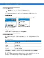
Page 109: ...ess ENTER An exclamation point appears on the Bluetooth icon indicating that the Bluetooth radio is disabled Figure 6 1 Disable Bluetooth Enabling Bluetooth To enable Bluetooth press ALT B Use the navigation keys to select Enable Bluetooth Press ENTER The Bluetooth icon changes to indicate that Bluetooth is enabled Figure 6 2 Enable Bluetooth NOTE Turning the Bluetooth radio on and off using the f...

Page 110: ...ory If a profile is not used it can be removed to save memory To load or remove profiles 1 If BTExplorer is running press ALT B 2 Use the navigation keys to select Disable Bluetooth and then press ENTER 3 Open BTProfileSelector using the Start menu a Press CTRL ESC to open the Start menu b Use the navigation keys to highlight Programs c Press the right arrow key to open the Programs menu d Use the...

Page 111: ...r the Deselect All button to deselect all profiles 7 Press TAB to place focus on the Apply button 8 Press Space or ENTER to apply any changes 9 Press TAB to place focus on the Close button 10 Press Space to exit Profile Selector 11 Press ALT B Use the navigation keys to select Enable Bluetooth to enable the BTExplorer application See Services Tab on page 6 23 for more information on selecting serv...

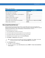
Page 112: ...ed device and navigation within the BTExplorer application is performed using the keypad Refer to the WT4070 90 Wearable Terminal User Guide for detailed information on keypad navigation Key Combinations The wearable terminal uses special key combinations to easily navigate applications Table 6 2 lists the key combinations required to perform various application navigation and control functions NO...

Page 113: ...r 5 Press ENTER The BTExplorer window appears 6 From the Favorite window a Press ALT F to open the File menu b Use the navigation keys to select New Connection and press ENTER The New Connection Wizard window appears Table 6 2 Key Combinations Action Combination Access the Start menu on the taskbar CTRL ESC Switch fields within an application TAB Close windows or cancel operations on some applicat...

Page 114: ...to Internet using Phone Modem Connect to Personal Area Network Connect to Printer Send or Exchange Objects Associate Serial Port 8 Press ENTER BTExplorer searches for Bluetooth devices in the area and displays the devices in the Select Remote Device window Figure 6 6 Device Discovery Dialog Box NOTE If a device discovery action has not been previously performed a device discovery is automatically ...

Page 115: ...nd press ENTER The Connection Favorite Options window appears Figure 6 9 Connection Favorite Options Window 11 Press TAB to highlight the Favorite Name text box enter a name for this service that will appear in the Favorite window 12 Press ENTER The Connection Summary window appears NOTE To filter devices in the list press ALT F to open the filter menu Select a device type and then press ENTER To ...

Page 116: ...xamples of available services are File Transfer Services Headset Services OBEX Object Push Services Serial Port Services Personal Area Network Services HID Services These services are discussed in the following paragraphs File Transfer Services To transfer files between the wearable terminal and another Bluetooth enabled device 1 In the Favorite window use the navigation keys to select the file tr...

Page 117: ...ct a folder to place the file into 8 Press ENTER 9 Press ENTER to save the file 10 Select the action to perform a New create a new file or folder on the remote device b Delete delete the selected file on the remote device c Get File copy the file from the remote device to the wearable terminal d Put File copies a file from the wearable terminal to the remote device e Parent Directory opens the hig...

Page 118: ...is created on the remote device Delete File To delete a file from the remote device 1 Use the navigation keys to select the file to delete 2 Press MENU to open the pop up menu 3 Use the navigation keys to select Delete 4 Press ENTER A Delete Remote Device File dialog box appears 5 Press ENTER to delete the file Get File To copy a file from a remote device to the wearable terminal 1 Press MENU to o...

Page 119: ... ENTER The Send Local File window appears Figure 6 16 Send Local File Window 5 Press TAB three times to enter the folder area 6 Select a file in the wearable terminal 7 Press ENTER The Sending Local File window appears Figure 6 17 Sending Local File Window 8 The file is transferred from the wearable terminal to the remote device Connect to Internet Using Access Point This section explains how to a...

Page 120: ...ng pictures to be shared using Bluetooth To send a picture to another device 1 In the Favorite window use the navigation keys to select the OBEX Push service 2 Press MENU and select Connect from the pop up menu 3 Press ENTER The OBEX Object Push window appears Figure 6 18 OBEX Object Push Window 4 Press TAB twice to highlight the button 5 Press SPACE 6 The Send Local Picture window appears Figure ...

Page 121: ...r headset user manual for instruction on communicating with a Bluetooth device Serial Port Services Use the wireless Bluetooth serial port connection just as you would a physical serial cable connection You must configure the application that will use the connection to the correct serial port To establish a serial port connection 1 In the Favorite window use the navigation keys to select the Seria...

Page 122: ... 1 In the Favorite window use the navigation keys to select the Personal Area Network service 2 Press MENU and select Connect from the pop up menu 3 The wearable terminal connects to the Personal Area Network HID Services Connect input devices such as Bluetooth keyboards and mice to the wearable terminal To establish a HID connection 1 In the Favorite window use the navigation keys to select the H...

Page 123: ...ow appears 2 Press ALT F to open the File menu 3 Use the navigation keys to select New Connection and press ENTER The New Connection Wizard window appears Figure 6 22 New Connection Wizard Window 4 Use the navigation keys to select Pair with Remote Device 5 Press ENTER The BTExplorer searches for Bluetooth devices in the area and displays the devices in the Select Remote Device window Figure 6 23 ...

Page 124: ...vice name moves to the Trusted Devices window Accepting a Bond When a remote device wants to bond with a wearable terminal you give permission by entering a PIN when requested 1 Ensure that the wearable terminal is set to discoverable and connectable See Bluetooth Settings on page 6 23 2 When prompted to bond with the remote device the PIN Code Request window appears NOTE To filter devices in the ...

Page 125: ...es Window The Trusted Devices window lists all bonded devices To access the Trusted Devices window 1 Launch BTExplorer 2 Press ALT T 3 Using the navigation keys select Trusted Devices 4 Press ENTER The Trusted Devices window appears Figure 6 27 Trusted Device Window The Trusted Devices window contains one menu that can be accessed through key combinations It allows you to change the window listing...

Page 126: ...ct Delete Link Key 4 Press ENTER A confirmation dialog box appears 5 Press ENTER to confirm deletion of the trusted device 6 Press ENTER to exit the Trusted Device window Connecting to a Favorite Service The Favorite window can display many services set as favorites To connect to one of these services 1 Use the navigation keys to select the service 2 Press ENTER 3 The wearable computer connects to...

Page 127: ...he View menu press ALT V To open the Tools menu press ALT T Delete all Favorite Services To delete all favorites from the Favorites window 1 Press ALT F 2 Use the navigation keys to select Delete All Favorites 3 Press ENTER A confirmation dialog box appears 4 Press ENTER to confirm the deletion or ESC to cancel the deletion Delete a Favorite Service To delete a selected favorite 1 Use the navigati...

Page 128: ...The Favorite window layout changes View Active Connections To view active connections 1 Press ALT T 2 Use the down arrow key to select Active Connections 3 Press ENTER The Active Connections window appears 4 Press ENTER to close the window View Properties To view the properties of the wearable terminal 1 Press ALT T 2 Use the down arrow key to select Local Device Properties 3 Press ENTER The Local...

Page 129: ...nfo Tab Press TAB to move to the next field Services Tab Use the Services tab to management of the services the wearable terminal makes available for use by other Bluetooth devices Table 6 3 Device Info Tab Field Description Device Name Displays the name of the wearable terminal Not editable Discoverable Mode Allows you to set the wearable terminal to be discoverable by other Bluetooth devices or ...

Page 130: ...e the navigation key to select a service to add 3 Press ENTER to accept the service Press ESC to exit without saving The Edit Local Service window displays for the selected service 4 Select the appropriate information and then Press ENTER See the following paragraphs for detailed information on the available services File Transfer Service File transfer allows files to be browsed by other Bluetooth...

Page 131: ... list None Authenticate or Authenticate Encrypt Root Directory Select the directory that other Bluetooth devices can access File Permissions Select the file permissions for the selected directory Check the appropriate box to grant Read access write access and delete access Table 6 5 OBEX Exchange Information Window Field Description Service Name Displays the name of the service Service Security Se...

Page 132: ...Window Field Description Service Name Displays the name of the service Service Security Select the type of security from the drop down list None Authenticate or Authenticate Encrypt Support Group Ad Hoc Networking Select to enable Ad Hoc networking Table 6 7 Serial Port Service Window Field Description Service Name Displays the name of the service Service Security Select the type of security from ...

Page 133: ... Local COM Port Select the COM port Select COM1 to use a modem or other device that is connected to the connector on the bottom of the wearable terminal Local Baud Rate Select the communication baud rate Local Port Options Select the port option Field Description Service Name Displays the name of the service Field Description Service Name Displays the name of the service Table 6 7 Serial Port Serv...

Page 134: ...Tab Use the Discovery tab to set and modify discovered devices Table 6 8 Security Tab Field Description Use PIN Code Incoming Connecting Select for automatic use of the PIN code entered in the PIN Code text box It is recommended not to use this automatic PIN code feature See Security on page 6 2 for more information PIN Code Enter the PIN code Encrypt Link On All Outgoing Connections Select to ena...

Page 135: ...takes to discover Bluetooth devices in the area Name Discovery Mode Select either Automatic or manual Discovered Devices buttons Deletes all discovered devices and link keys Table 6 10 Virtual COM Port Screen Field Description COM4 Bluetooth Enable or disable COM Port 4 COM5 Bluetooth Enable or disable COM Port 5 COM9 Bluetooth Enable or disable COM Port 9 NOTE If an application uses one of the CO...

Page 136: ...lorer Settings Miscellaneous Tab NOTE The HID tab only appears if HID is selected in the Bluetooth Profile Selector application See Bluetooth Profiles on page 6 4 for more information Table 6 11 HID Tab Field Description Enable Key Repeat Enable the Delay and Rate settings Delay Sets the amount of time that elapses before a character repeats when you hold down a key Rate Sets the speed at which a ...

Page 137: ...ht Connections Select the connection type to highlight when connected In the Wizard Mode the only option is Favorites or None Apply Text Style Select the text style to be applied to the connection text Apply Text Color Select the text color to be applied to the connection text ...

Page 138: ...6 32 WT4070 90 Wearable Terminal Integrator Guide ...

Page 139: ... new Windows CE device type and its associated libraries onto the development PC The Device Configuration Package DCP is required to create and download hex images that represent flash partitions to the wearable terminal The DCP includes the user documentation flash partitions Terminal Configuration Manager TCM and the associated TCM scripts Device Configuration Package To install the DCP for WT40...

Page 140: ...s To install an EMDK 1 Download the EMDK from the Support Central web site http www zebra com support a On http www zebra com support select Developer Downloads and sign in b Select Mobile Computers and then select WT4000 c Select the latest version of the Symbol Mobility Developer Kit d Download the exe file to the development computer 2 Double click the executable file and follow the install scr...

Page 141: ...e Loader application finds the appropriate file it loads the package onto the wearable terminal 9 When complete the wearable terminal re boots ActiveSync Use ActiveSync to copy files from a host computer to the wearable terminal Ensure that ActiveSync is installed and that a partnership has been created see Chapter 3 ActiveSync 1 Connect the wearable terminal to the host computer using a USB cradl...

Page 142: ...d in this folder are discarded after a cold boot Application folder files stored in this folder are retained after a cold boot IPL Use IPL to download files onto the wearable terminal to download customized flash file system partitions to the wearable terminal and load hex files to the flash memory of the wearable terminal There are two types of update supported by the wearable terminal partitions...

Page 143: ...ng the Hex Image Using IPL on page 7 11 for procedures on downloading a hex file to the wearable terminal Creating Hex Images Terminal Configuration Manager TCM is an application used to customize flash file system partitions for the wearable terminal The most common use is to create an application partition hex file that contains the customer s application TCM can also be used to load hex files t...

Page 144: ...ript1 and File Explorer The Script1 window contains a newly created script and the File Explorer window contains a file explorer view used for selecting files to be placed in the script Figure 7 3 TCM Startup Window The following table lists the components of the TCM window Table 7 1 TCM Components Icon Component Function Script Window Displays the files to be used in the creation of the partition...

Page 145: ...utton View the current script items as small icon List button View the current script items as a list Details button View the current script items with more details About button Display version information for TCM Properties button View change the current script properties Build button Build the current script into a set of hex files Check button Check the script for errors files not found Send bu...

Page 146: ...racts it from another 7 In the Access drop down list for each disk partition determine and select the Read Write access option 8 Click the Options tab The Script Properties window Options tab appears Figure 7 5 Script Properties Window Options Tab 9 Set the paths for the Script File Flash File and Hex File Build 10 Click OK Creating the Script for the Hex Image On start up TCM displays the TCM win...

Page 147: ...ed with an older version of TCM The Conversion window appears automatically Figure 7 6 Conversion Window Upgrading to TCM 2 0 Copying Components to the Script Script contents are managed using standard file operations such as New Folder Delete and Rename Items can be added to the script by clicking files and folders in the File Explorer window and dragging them to the Script window The File Explor...

Page 148: ...lt is the Splash Screen a prompt appears requesting both the source Bitmap file and the destination HEX file 6 A check is performed and if there are no errors the partition hex files are created If the build fails the hex files are not be created and TCM displays an error message Two of the most common reasons for a build failure are Files defined in the script can not be found This error can occu...

Page 149: ...nal must be inserted in the cradle with appropriate power supply connected to a power source for the wearable terminal to reset into IPL Initial Program Loader Platform Application Config Block Windows CE Monitor Splash Screen Power Micro Partition Table Command File System Reset Auto Select CAUTION To insure a successful download do not remove power from the wearable terminal while in IPL mode NO...

Page 150: ...eral system resources In the unlikely event that the Power Micro Firmware needs updating selecting this item allows the device to be programmed Partition Table Contains the partition information for all other partitions Note The partition table should never need changing unless the sizes of the platform and application images are changed within TCM If this is done then the new partition table shou...

Page 151: ...llow the screen prompts 6 The USB Configuration menu appears 7 Select USB Standard and press ENTER The Download File menu appears Figure 7 11 Download File Menu 8 Use the up and down scroll buttons to select Show Parms to verify the file to download Press ENTER to display the Parameters screen USB Configuration USB Standard Previous Top Download File Download Cancel Show Parms Previous Top ...

Page 152: ...se the up and down scroll buttons to select Download Press Enter The Downloading screen appears Figure 7 13 Downloading Screen 11 On the development computer click Load on the TCM toolbar The Load Terminal window Serial tab appears Figure 7 14 Load Terminal Window Serial and Ethernet Tabs Download Partition Name via USB USB Standard Press Enter to continue Downloading Partition Name via USB USB St...

Page 153: ...CM toolbar The Load Terminal window Serial tab appears Figure 7 15 Load Terminal Window Serial and Ethernet Tabs 5 Select the Image Files To Load 6 In the Comm Port drop down list select USB Symbol Device 7 Click Download to begin the operation As soon as the download starts all three LEDs turn on and then the three LEDs indicate the progress of the download When 33 is completed the first LED turn...

Page 154: ... is selected to build Illegal ESS ID In the Build ESSID Partition window no ESS ID was entered or the ESS ID entered was illegal Disk Full TCM failed to create Hex image file at the selected path Check available disk space Target Disk Full Build process failed because TCM failed to add file to the image of a disk volume Remove some files or increase the disk size Hex file is READ ONLY The Hex imag...

Page 155: ...ME In Script Properties window one of the volume labels is not valid Corrupt TCM INI file Invalid value of VolumeDivisor The VolumeDivisor entry is missing or invalid in the TCM ini Reinstall TCM or recover TCM ini Invalid version of TCM script file The TCM script was not created by this version of TCM Corrupt or missing TCM ini file TCM could not find TCM ini file FAILED CONNECTION TO COM PORT Co...

Page 156: ...sh ROM or Power Micro could not be written to Retry the download If the failure persists it is most likely due to a hardware failure the wearable terminal requires servicing Transmission checksum error 11 An error occurred during transmission from the source device either radio card or Serial port and the checksum check failed Check source device connectivity and retry Readback checksum error 12 A...

Page 157: ...loaded file specifies a partition entry that does not exist on the device Only download files that are valid for this device or change the partition table so that the new file is valid on the device Wrong destination code 28 A specific partition was chosen from the Main Menu not Auto Select but the file selected for download was for another partition Ensure that the partition selected from the Mai...

Page 158: ...ontent of this partition Application The Application FFS partition is used to store application programs needed to operate the wearable terminal On Board IDE An additional 64 MB of FLASH memory available only on 128 MB 128 MB configurations This partition can be used for additional application or data storage Working with FFS Partitions Because the FFS partitions appear as folders under the Window...

Page 159: ...The warm boot does not re initialize the registry and the early loading driver reads the new registry values Do not use Regmerge to modify built in driver registry values or merge the same Registry value to two files in the same folder as the results are undefined CopyFiles Windows CE expects certain files to be in the Windows folder residing in volatile storage Windows CE maintains the System Reg...

Page 160: ...e terminal cold boots To download a customized screen to display see Creating a Splash Screen on page 7 19 IPL This program interfaces with the host computer and allows downloading via cradle or serial cable any or all of the partitions listed above as well as updated versions of IPL Use caution downloading updated IPL versions incorrect downloading of an IPL causes permanent damage to the wearabl...

Page 161: ...and MSP3 Agent clients Rapid Deployment RD Client The RD Client provides support for MSP 3 Staging functionality provides support for the MSP 3 Legacy Staging process and provides support for backward compatible legacy MSP 2 x Legacy Staging functionality AirBEAM Smart Client The AirBEAM Smart Client provides backward compatible legacy AirBEAM functionality and backward compatible legacy MSP 2 x L...

Page 162: ...8 2 WT4070 90 Wearable Terminal Integrator Guide ...

Page 163: ... the touch points at least 2 mm in from the edge Tips for Improving Battery Life To improve the life of the battery Set the display backlight to turn off quickly and reduce the display brightness Set the keypad backlight to turn off quickly Set the wearable computer to suspend when not is use and maximum CPU performance Set the WLAN radio to save maximum power After making these settings they can ...

Page 164: ... a lower value that the user is comfortable with To disable the key light from coming on 1 Select the Advanced tab 2 Ensure that the Disable keylight checkbox is checked Tap OK Power To set the wearable computer to turn off after a short period of non use 1 Select Start Settings Control Panel 2 Select Power icon 3 Select Power Off tab 4 Ensure that the Turn off device if not used for checkbox is c...

Page 165: ...e MAX Power Save radio button is selected Voice Only WT4090 LED Considerations Application developers for the Voice Only WT4090 should not program all LEDs to be turned on at the same time as this sequence is reserved for IPL mode Do not turn off the display backlight or the keypad backlight as this will turn off the Application Controlled LED and the WLAN Status LED respectively Consider device b...

Page 166: ...9 4 WT4070 90 Wearable Terminal Integrator Guide ...

Page 167: ...touch screen Zebra requires using this to minimize wear and tear Screen protectors enhance the usability and durability of touch screen displays Benefits include Protection from scratches and gouges Durable touch surface with tactile feel Abrasion and chemical resistance Keeping the device s screen looking new Quick and easy installation Protect the wearable computer with a touch screen from tempe...

Page 168: ...sary to wash the arm sleeve when it become soiled Hand wash in cold water with a mild detergent such as Woolite Do not use bleach Air dry Do not use a dryer Removing the Screen Protector A screen protector is applied to the wearable terminal with touch screen Zebra mandates using this to minimize wear and tear Screen protectors enhance the usability and durability of touch screen displays To remov...

Page 169: ...Do not disassemble or open crush bend or deform puncture or shred Severe impact from dropping any battery operated device on a hard surface could cause the battery to overheat Do not short circuit a battery or allow metallic or conductive objects to contact the battery terminals Do not modify or remanufacture attempt to insert foreign objects into the battery immerse or expose to water or other li...

Page 170: ...f liquid around the edges of the display Immediately dried the display with a soft non abrasive cloth to prevent streaking For WT4090 with touch panel only use a soft lens cloth to clean the touch panel overlay surface Connectors Clean all three connectors two interface connectors on the sides of the wearable terminal and the cradle connector on the back 1 Remove the main battery from mobile compu...

Page 171: ...uch as eyeglasses Connectors 1 Disconnect the scanner from mobile computer 2 Dip the cotton portion of the cotton tipped applicator in isopropyl alcohol 3 Rub the cotton portion of the cotton tipped applicator back and forth across the connector pins Do not leave any cotton residue on the connector 4 Repeat at least three times 5 Use the cotton tipped applicator dipped in alcohol to remove any gre...

Page 172: ... However when used in dirty environments it may be advisable to periodically clean the ring scanners exit windows to ensure optimum scanning performance Troubleshooting Wearable Terminal CAUTION Do not point nozzle at yourself and others ensure the nozzle or tube is away from your face 8 Allow at least 10 to 30 minutes depending on ambient temperature and humidity for the alcohol to air dry before...

Page 173: ...ion Screen protector may be scratched or worn Replace screen protector During data communication no data was transmitted or transmitted data was incomplete Wearable terminal removed from cradle or unplugged from host computer during communication Replace the wearable terminal in the cradle or reattach the Synchronization cable and re transmit Incorrect cable configuration See the System Administra...

Page 174: ...t disabled Battery is depleted Replace or recharge the battery Battery is not inserted properly Insert the battery properly see Installing and Removing the Main Battery on page 1 4 The wearable computer s battery is low and it powers down to protect memory content Replace or recharge the battery A message appears stating that the wearable terminal memory is full not applicable to voice only config...

Page 175: ... the scanner shuts off before the wearable terminal low battery condition notification Note If the scanner is still not reading symbols contact the distributor or Zebra Wearable terminal goes into IPL mode after cold boot Headset adapter without a headset is connected to the wearable terminal during a cold boot Disconnect the headset adapter prior to performing a cold boot Scanner trigger is held ...

Page 176: ...he Four Slot Ethernet Cradle Problem Cause Solution Wearable terminal amber Charge Status LED does not light when wearable terminal inserted Cradle is not receiving power Ensure the power cable is connected securely to both the cradle and to AC power Wearable terminal is not correctly seated Remove and re insert the wearable terminal into the cradle ensuring it is correctly seated Wearable termina...

Page 177: ... firmly in the cradle Remove and re insert the spare battery into the charging slot ensuring it is firmly seated Wearable terminal battery is not charging Wearable terminal was removed from cradle or cradle was unplugged from AC power too soon Ensure cradle is receiving power Ensure wearable terminal is seated correctly Confirm main battery is charging View battery status by selecting Start Settin...

Page 178: ...er 2 Accessories Ensure that Microsoft ActiveSync 4 1 or greater is installed on the host computer Cannot ActiveSync with Host Computer Wrong USB cable used Ensure that the cable has a USB A connector on one end and a USB mini B connector on the other end Host computer not configured properly Ensure that ActiveSync on the host computer is set to allow USB connections The wearable computer is not f...

Page 179: ...m H With Extended Battery 5 7 inches L x 4 2 inches W x 1 0 inch H 14 2 cm L x 10 7 cm H x 2 6 cm H Weight including battery With Standard Battery 11 3 oz 320 g With Extended Battery 12 2 oz 345 g Keyboard WT4070 90 Two color Alphanumeric Keypad or Triple tap Alphanumeric Keypad Voice Only WT4090 Three programmable function keys Display WT4070 90 Color 2 8 inch QVGA non touch or touch screens Voic...

Page 180: ...ESD 15k VDC air discharge 8k VDC direct discharge 8k VDC indirect discharge WLAN Wireless Data Communications WLAN radio WT4070 Zebra 802 11b g WT4090 Zebra 802 11a b g Operating Channels Channel 8 169 5040 5845 MHz 4920 4980 MHz Japan only Channel 1 13 2412 2472 MHz Channel 14 2484 MHz Japan only Actual operating frequencies depend on regulatory rules and certification agency Security WEP2 40 or ...

Page 181: ...Specifications A 3 Antenna Internal WPAN Wireless Data Communications Bluetooth Bluetooth Version 1 2 Table A 1 Technical Specifications Continued Item Description ...

Page 182: ...RSS 210 ARIB STD 66 33 ARIB STD T70 71 Table A 1 Technical Specifications Continued Item Description Table A 2 RS309 Technical Specifications Item Description Physical and Environmental Characteristics Dimensions standard version without cables attached 2 7 inch L x 2 4 inch W x 1 5 inch H 6 8 cm L x 6 1 cm H x 3 8 cm Weight standard version without cables attached 3 525 oz 98 gm Current 140 mA ty...

Page 183: ...ralian AS NZS 4268 Laser Safety CDRH Class II IEC 60825 1 Class 2 Laser Decode Capability Code 39 Code 128 Code 93 Codabar Code 11 Discrete 2 of 5 Interleaved 2 of 5 EAN 8 EAN 13 MSI UPCA UPCE UPC EAN supplementals Coupon Code Trioptic 39 Webcode Chinese 2 of 5 RSS Table A 2 RS309 Technical Specifications Continued Item Description Table A 3 RS409 Technical Specifications Item Description Physical...

Page 184: ...idity 5 to 95 non condensing Drop Specification 4 ft 1 8m drop to concrete Environmental Sealing IP54 sealing Ambient Light Immunity Indoor 450 foot candles 4 844 lux Outdoor 8 000 foot candles 86 111 lux Regulatory Electrical Safety Certified to CSA C22 2 No 60950 1 EN60950 1 IEC 60950 1 EMI RFI FCC Part 15 Class B ICES 003 Class B European Union EMC and R TTE Directives Australian AS NZS 4268 La...

Page 185: ...2 oz Triggered standard battery 134 8 g 4 8 oz Triggered corded 140 8 g 5 0 oz Performance Characteristics Optical Resolution WVGA 752 H x 480 V pixels gray scale Skew 60 from normal Roll 360 Pitch 60 from normal Aiming Element 655 nm 10 nm Visible Laser Diode Illumination Element 637 nm 5 nm Red LEDs Field of View Horizontal 39 6 Vertical 25 7 Nominal Working Distance Density 5 mil 7 5 mil 20 mil...

Page 186: ... 1 with Adaptive Frequency Hopping AFH Supported profiles Serial Port Profile SPP Human Interface Device Profile HID Service Discovery Application Profile SDAP Pairing by reading terminal BT address as bar code off the display or from a printed label Corded to WT4090 Serial Field Replaceable Parts Batteries corded adaptor trigger clamp triggerless clamp comfort pad straps and strap buckle User Int...

Page 187: ...CDRH Class II IEC 60825 1 Class 2 RoHS Compliance with RoHS standards Table A 4 RS507 Technical Specifications Continued Item Description Table A 5 Accessory Specifications Single Slot USB Cradle Four Slot Ethernet Cradle Four Slot Spare Battery Charger Operating Temperature 32 F to 122 F 0 C to 50 C 32 F to 104 F 0 C to 40 C Storage Temperature 40 F to 158 F 40 C to 70 C Battery Charging Temperat...

Page 188: ... host negative 3 GND Digital system ground 4 USBH_P_RIGHT USB host positive 5 A_GND Analog ground 6 HPOUTL_RIGHT_MIC Mic default or headphone out left 7 U2_RXD Scanner serial RXD 8 HPOUTER_RIGHT Headphone out right 9 U2_TXD Scanner serial TXD 10 SCAN_PWR Scanner 3 3 VDC power out 11 U2_CTS Scanner serial CTS default if laser scanner plugged in or Audio Ground sense MIC default if audio connector p...

Page 189: ...al Name Function 1 Power In 5 4 VDC input power 2 ACC_OTG_VBUS 5 0 VDC input in client mode 5 0 VDC output in host mode 3 ACC_OTG_DP USB data positive 4 ACC_OTG_DM USB data negative 5 System GND System ground 6 ACC_OTG_ID USB host client ID pin input Low USB Host High USB Client 7 System Ground System ground Pin 1 ...

Page 190: ...A 12 WT4070 90 Wearable Terminal Integrator Guide ...

Page 191: ...s phones medical and scientific equipment as well as Bluetooth devices all work within the 2 4 GHz ISM band 802 11g Similar to 802 11b but this standard supports signaling rates of up to 54Mbit sec It also operates in the heavily used 2 4 GHz ISM band but uses a different radio technology to boost overall throughput Compatible with the 802 11b A Access Point Provides a bridge between Ethernet wire...

Page 192: ... one byte of data The pattern of 0 and 1 values within the byte determines its meaning Bits per Second bps Bits transmitted or received Bluetooth A low cost short range radio link between two devices Bluetooth can replace cables and can be used to create ad hoc networks and provide a standard way to connect devices Bit Binary digit One bit is the basic unit of binary information Generally eight co...

Page 193: ...encoded check digit Check digits are required for UPC but are optional for other symbologies Using check digits decreases the chance of substitution errors when a symbol is decoded Cold Boot A cold boot restarts the wearable terminal and erases all user stored records and entries COM port Communication port ports are identified by number e g COM1 COM2 Continuous Code A bar code or symbol in which ...

Page 194: ...mbination of digital certificates and another system such as passwords EAP TLS Extensible Authentication Protocol Transport Layer Security A mutual authentication method that uses digital certificates Encoded Area Total linear dimension occupied by all characters of a code pattern including start stop characters and data Encryption Encoding data to prevent it from being read by unauthorized people...

Page 195: ...P communications protocol IP implements the network layer layer 3 of the protocol which contains a network address and is used to route a message to a different network or subnetwork IP accepts packets from the layer 4 transport protocol TCP or UDP adds its own header to it and delivers a datagram to the layer 2 data link protocol It may also break the packet into fragments to support the maximum ...

Page 196: ...to reflect their information to the user M MC Mobile computer MDN Mobile Directory Number The directory listing telephone number that is dialed generally using POTS to reach a mobile unit The MDN is usually associated with a MIN in a cellular telephone in the US and Canada the MDN and MIN are the same value for voice cellular users International roaming considerations often result in the MDN being...

Page 197: ...ly devices within this limited area typically participate in the network Parameter A variable that can have different values assigned to it PING Packet Internet Groper An Internet utility used to determine whether a particular IP address is online It is used to test and debug a network by sending out a packet and waiting for a response Programming Mode The state in which a scanner is configured fo...

Page 198: ...crosoft and other Internet client server developers as well and became the de facto standard until evolving into Transport Layer Security The sockets part of the term refers to the sockets method of passing data back and forth between a client and a server program in a network or between program layers in the same computer SSL uses the public and private key encryption system from RSA which also i...

Page 199: ...n on a remote non mainframe terminal including all display features commands and function keys The WT4090 Series supports Terminal Emulations in 3270 5250 and VT220 TFTP Trivial File Transfer Protocol A version of the TCP IP FTP File Transfer Protocol protocol that has no directory or password capability It is the protocol used for upgrading firmware downloading software and remote booting of disk...

Page 200: ...lone device or it can be set up to communicate with a network using wireless radio technology WEP Wired Equivalent Privacy protocol was specified in the IEEE 802 11 standard to provide a WLAN with a minimal level of security and privacy comparable to a typical wired LAN using data encryption WPA Wi Fi Protected Access is a data encryption specification for 802 11 wireless networks that replaces th...

Page 201: ...16 AFH 6 1 AP networks 5 34 authentication 5 7 EAP TLS 5 8 LEAP 5 8 none 5 8 PEAP 5 8 tunneled 5 8 automatic time setting 5 36 B backup battery charging 1 5 band selection 2 4 GHz 5 35 5 GHz 5 35 battery backup charging 1 5 charging 1 5 temperature range A 9 check status 1 7 installing 1 4 removing 1 6 battery charging temperature A 2 battery management 1 8 bluetooth adaptive frequency hopping 6 1...

Page 202: ...ading files 7 3 drop specification A 2 A 5 A 6 A 8 E EAP TLS 5 8 edit a profile 5 4 electrical safety A 4 A 5 A 6 A 9 EMDK for eVC4 xvii encryption 5 15 open system 5 16 5 18 TKIP WPA 5 16 Enterprise Mobility Developer Kit for eVC4 xvii error messages 7 16 7 17 exporting a profile 5 24 5 37 F Fast Power Save 5 21 file explorer 7 6 finding access points 5 3 finding WLAN networks 5 3 flash file syst...

Page 203: ...2 IPL 7 22 splash screen 7 22 parts of the wearable terminal 1 1 1 2 1 3 PassKey 5 17 password 5 14 PEAP 5 8 ping 5 31 pin outs wearable terminal A 10 power settings 1 9 power supply 2 14 profile create new 5 24 delete 5 24 edit 5 4 profile ID 5 4 profile name 5 5 profile persistence 5 38 profile roaming 5 36 programs flash file system 7 20 R radios xiv registry settings 5 38 regulatory options 5 ...

Page 204: ...temperature battery charging A 9 TKIP 5 16 TKIP WPA 5 16 transmit power automatic 5 20 power plus 5 20 troubleshooting 10 6 four slot spare battery charger 10 10 turn the radios off saving power 1 10 U unpacking 1 1 user certificate 5 10 user name 5 14 W wall mounting bracket 2 13 mounting multiple brackets 2 19 wiring 2 17 warm boot 1 8 6 4 wearable terminal cold boot 7 21 starting 1 7 weight A 1...

Page 205: ......
Page 206: ... Lincolnshire IL U S A http www zebra com Zebra and the stylized Zebra head are trademarks of ZIH Corp registered in many jurisdictions worldwide All other trademarks are the property of their respective owners 2015 ZIH Corp and or its affiliates All rights reserved ...

Reviews: