


3- 24
MC68306 USER'S MANUAL
MOTOROLA
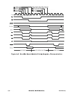
BUS THREE-STATED
BG ASSERTED
BR VALID INTERNAL
BR SAMPLED
BR ASSERTED
BUS RELEASED FROM THREE STATE AND
PROCESSOR STARTS NEXT BUS CYCLE
BR NEGATED INTERNAL
BR SAMPLED
BR NEGATED
BR
BG
BGACK
AS
UDS
LDS
R/W
DTACK
D15–D0
S0
S2
S4
S6
S0
S2
S4
S6
S0
CLK
FC2–FC0
A31–A1
PROCESSOR
ALTERNATE BUS MASTER
PROCESSOR
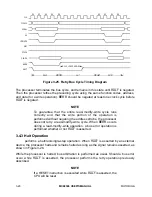
Figure 3-23. Two-Wire Bus Arbitration Timing Diagram—Special Case
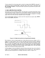
3.4 BUS ERROR AND HALT OPERATION
In a bus architecture that requires a handshake from an external device, such as the
asynchronous bus used in the M68000 Family, the handshake may not always occur. A
bus error input is provided to terminate a bus cycle in error when the expected signal is
not asserted. Different systems and different devices within the same system require
different maximum-response times. External circuitry can be provided to assert the bus
error signal after the appropriate delay following the assertion of address strobe.
3.4.1 Bus Error Operation
A bus error is recognized when
BERR
is asserted,
HALT
is negated, and
DTACK
is not
asserted before
BERR
(or not at all).
When the bus error condition is recognized, the current bus cycle is terminated in S7
(
DTACK
and
BERR
together) or S9 (
BERR
alone) for a read cycle, a write cycle, or the
read portion of a read-modify-write cycle. For the write portion of a read-modify-write
cycle, the current bus cycle is terminated in S19 (
DTACK
and
BERR
together) or S21