


MOTOROLA
MC68306 USER'S MANUAL
7-3
7.2 TAP CONTROLLER
The TAP controller is responsible for interpreting the sequence of logical values on the
TMS signal. It is a synchronous state machine that controls the operation of the JTAG
logic. The state machine is shown in Figure 7-2; the value shown adjacent to each arc
represents the value of the TMS signal sampled on the rising edge of the TCK signal. For
a description of the TAP controller states, please refer to the IEEE 1149.1 document.
TEST LOGIC
RESET
RUN-TEST/IDLE
SELECT-DR_SCAN
CAPTURE-DR
SELECT-IR_SCAN
CAPTURE-IR
SHIFT-DR
SHIFT-IR
EXIT1-DR
EXIT1-IR
PAUSE-DR
PAUSE-IR
EXIT2-DR
UPDATE-DR
EXIT2-IR
UPDATE -IR
1
0
1
1
0
1
0
0
1
0
1
0
0
1
1
1
0
0
1
0
1
1
1
0
1
1
0
0
0
0
0
1
Figure 7-2. TAP Controller State Machine
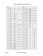
7.3 BOUNDARY SCAN REGISTER
The MC68306 IEEE 1149.1 implementation has a 124-bit boundary scan register. This
register contains bits for all device signal and clock pins and associated control signals.