


MOTOROLA
MC68306 USER'S MANUAL
6-21
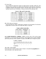
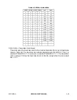
Table 6-3. CMx Control Bits
CM1
CM0
Mode
0
0
Normal
0
1
Automatic Echo
1
0
Local Loopback
1
1
Remote Loopback
TxRTS—Transmitter Ready-to-Send
This bit controls the negation of the
RTSA
or
RTSB
signals. The output is normally
asserted by setting OP0 or OP1 and negated by clearing OP0 or OP1 (see 6.4.1.18
Output Port Control Register (DUOPCR)).
1 = In applications where the transmitter is disabled after transmission is complete,
setting this bit causes the particular OP bit to be cleared automatically one bit
time after the characters, if any, in the channel transmit shift register and the
transmitter holding register are completely transmitted, including the programmed
number of stop bits. This feature is used to automatically terminate transmission
of a message. If both the receiver and the transmitter in the same channel are
programmed for
RTS
control,
RTS
control is disabled for both since this is an
incorrect configuration.
0 = The transmitter has no effect on
RTS≈
.
TxCTS—Transmitter Clear-to-Send
1 = Enables clear-to-send operation. The transmitter checks the state of the
CTS≈
input each time it is ready to send a character. If
CTS≈
is asserted, the character
is transmitted. If
CTS≈
is negated, the channel TxDx remains in the high state,
and the transmission is delayed until
CTS≈
is asserted. Changes in
CTS≈
while a
character is being transmitted do not affect transmission of that character. If both
TxCTS and TxRTS are enabled, TxCTS controls the operation of the transmitter.
0 = The
CTS≈
has no effect on the transmitter.
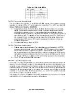
SB3–SB0—Stop-Bit Length Control
These bits select the length of the stop bit appended to the transmitted character as
listed in Table 6-4. Stop-bit lengths of nine-sixteenth to two bits, in increments of one-
sixteenth bit, are programmable for character lengths of six, seven, and eight bits. For a
character length of five bits, one and one-sixteenth to two bits are programmable in
increments of one-sixteenth bit. In all cases, the receiver only checks for a high
condition at the center of the first stop-bit position—i.e., one bit time after the last data
bit or after the parity bit, if parity is enabled.
If an external 1
×
clock is used for the transmitter, DUMR2 bit 3 = 0 selects one stop bit,
and DUMR2 bit 3 = 1 selects two stop bits for transmission.