Monosem SUPER-CROP C1L Assembly, Adjustment And Maintenance Instructions Download Page 45

SCD

43

MONTAGE GÉNÉRAL

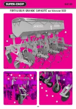
Le  montage  des  éléments  bineurs  s’effectue  comme  sur  les  bineuses
classiques, notices pages 12 à 15. Les éléments à tête spécifique 11520.1
Fig. 89 page 42 sont à placer de chaque côté de l’élément central et ceci
pour n’importe quels inter-rangs. Les vérins de repliage sont à brocher
suivant Fig. 93, page 42 : 
- Dans le trou "A" pour un inter-rangs de 45 cm.
- Dans le trou "B" pour des inter-rangs de 50 - 75 - 80 cm
Les crochets de verrouillage 11389 possèdent deux positions
- Suivant Fig. 86 pour un inter-rangs de 45 cm
- Suivant Fig. 87 pour des inter-rangs de 50 - 75 - 80 cm
De plus, les trous oblongs permettent d’affiner le réglage.

Au moment du repliage, pour un inter-rangs de 80 cm, il est indis-

pensable de placer la cale 11528 sur les éléments latéraux Fig. 90.

Attelage au tracteur. Les 2 points inférieurs d’attelage sont réglables

en  écartement.  Les  2  bras  de  relevage  du  tracteur  doivent  être  rigides
(non-flottants), chaînes tendues. Le réglage de la hauteur du châssis  3  se
fait  par  les  roues  stabilisatrices  4  latérales.  Les  parallélogrammes 
d’éléments  doivent  être  horizontaux.  Vérifier  et  régler  par  le  3

ème

point 

l’aplomb général de la machine. Avant la mise en route, graissage des
axes  d’articulation  Fig  91  et  92.  Mise  en  route  page  suivante. 5  Disque 
de  traçage  arrière  à  laisser  en  place  si  l’utilisateur  désire  biner  de 
nouveau.

GENERAL ASSEMBLY

The  assembly  of  the  cultivator  units  is  the  same  as  on  the  traditional
cultivators,  manual  pages  12  to  15.  The  units  with  specific  heads  ref.
11520.1 Fig. 89 page 42 are to be positioned on each side of the central
unit and this for any inter row configuration. The folding cylinders are to
be pinned according to fig. 93 page 42 :
- In the hole "A" for an inter row spacing of 45 cm
- In the hole "B" for inter row spacings of 50 - 75 - 80 cm
The locking hooks 11389 have two positions :
- According to Fig. 86 for an inter row spacing of 45 cm
- According to Fig. 87 for inter row spacings of 50 - 75 - 80 cm
Furthermore, the oblong holes enable an improvement of the adjustment.

!

When folding, for an inter row spacing of 80 cm, it is essential to

position the wedge 11528 on the lateral units Fig. 90.

Hitching to tractor. The two lower linking points are adjustable in

width. The 2 lift arms of the tractor should be rigid (not floating), chains
stretched. The adjustment of the height of the frame  3  is made by the
lateral stabilizing wheels  4 . The unit parallelograms must be horizontal.
Check  and  adjust  the  3rd  point,  the  general  perpendicularity  of  the
machine. Before starting up, lubricate the articulation shafts Fig. 91 and
92. For starting up instructions see following page.  5  Rear tracing disc to
be left in place if the user wants to cultivate again.

MONTAGEANLEITUNG

Die  Montage  der  Hackelemente  erfolgt  wie  bei  den  klassischen
Hackmaschinen. Sehen Sie dazu die Anweisungen Seiten 12 bis 15. Die
mit Sonderkopf ausgerüsteten Elemente 11520.1 Abb. 89 lassen sich an
jede  Seite  des  Grundelements  für  irgendwelchen  Reihenabstand
anbauen. Die Klappzylinder sind nach Abb. 93, Seite 42 zu blockieren :
- im Loch "A" für einen Reihenabstand von 45 cm
- im Loch "B" für Reihenabstände von 50 - 75 - 80 cm
Die Verriegelungshaken 113899 erlauben zwei Stellungen :
- nach Abb. 86 für einen Reihenabstand von 45cm
- nach Abb. 87 für Reihenabstände von 50 - 75 - 80 cm
Ausserdem ermöglichen Langlöcher eine genauere Einstellung.

Während des Einklappens ist es nötig bei einem Reihenabstand von

80 cm, den Keil 11528 auf die seitlichen Elemente Abb. 90 anzubringen.

Anbau an den Schlepper. Der Abstand der 2 unteren Anbaupunkte ist

einstellbar. Die 2 Hebearme des Schleppers sind festzustellen (mit gespannten
Ketten).  Die  Höhe  des  Rahmens    3    läßt  sich  mittels  der  seitlichen
Stabilisierungsräder    4    einstellen.  Die  Elementparallelogramme  müssen
waagerecht  liegen.  Den  Oberlenker  so  prüfen  und  einstellen,  daß  der
Oberlenkeranbaublock  der  Maschine genau  senkrecht  steht.  Vor  der
Inbetriebsetzung  sind  die  Gelenkachsen Abb.  91  und  92  zu  schmieren.
Inbetriebsetzung  siehe  nächste  Seite.    5    Die  Hinterspurscheibe  sollte  nicht
versetzt werden, wenn der Benutzer nochmals hacken will.

MONTAGGIO GENERALE

Si  montano  gli  elementi  sarchiatrici  come  sulle  sarchiatrici  tradizionali;
vedere istruzioni pagine 12 a 15. Gli elementi a testa specifica 11520.1 fig.
89 pagina 42 sono da montare ai due lati dell'elemento centrale e questo
per  qualsiasi interfila. I cilindri di piegamento sono da bloccare secondo
Fig. 93, pagina 42 :
- nel foro "A" per interfila da 45 cm
- nel foro "B" per interfile da 50 - 75 - 80 cm
I ganci di bloccaggio 11389 possiedono due posizioni
- secondo fig. 86 per interfila da 45 cm
- secondo fig. 87 per interfile da 50 - 75 - 80 cm
Inoltre i fori oblunghi consentono una regolazione più precisa.

Nel momento del piegamento per un interfila da 80 cm é necessario

mettere il cuneo 11528 sugli elementi laterali fig. 90.

Attacco al trattore. Lo scartamento dei 2 punti inferiori di attacco é

regolabile. I 2 bracci di sollevamento del trattore devono essere rigidi (non
mobili), essendo tese le catene. La regolazione dell'altezza del telaio  3
avviene mediante le ruote stabilizzatrici  4  laterali. I parallelogrammi di
elementi  devono  essere  orizzontali.  Comprobare  e  aggiustare  tramite  il
terzo punto l'appiombo generale della macchina. Prima dell'avviamento,
lubrificare gli assi di articolazione Fig. 91 e 92. Avviamento, veda pagina
seguente.  5  Disco tracciatore posteriore non é da spostare se l'utente
vuole sarchiare di nuovo.

Summary of Contents for SUPER-CROP C1L

Page 1: ...ly Adjustment and Maintenance Instructions Bedienungsanleitung Einstellung Wartung Notizia di Montaggio Regolazione Manutenzione BINEUSES DE PR CISION PRECISION ROW CROP CULTIVATORS BINEUSES DE PR CIS...

Page 2: ...e RIBOULEAU MONOSEM factory at the phone number given on the last page of this manual The identification and manufacturers plate on your cultivator is ti be found on the tree point hitch of the machin...

Page 3: ...EUER FERTILIZZATORE GRANDES TR MIES HIGH CAPACITY HOPPERS 38 39 GROSSRAUMBEH LTER TRAMOGGE GRANDI EXTRA FORT F LEGER V DIRIGEABLES EXTRA STRONG F LIGHT V STEERING EXTRA STARK F LEICHTE V HACKMASCHINE...

Page 4: ...ge et de d telage doivent se faire avec pr caution 11 Lors du d telage assurez vous du bon positionnement des b quilles pour une bonne stabilit de la machine 12 Avant l attelage de la machine assurez...

Page 5: ...et c t machine ne sont pas sous pression avant tout branchement de flexible au circuit hydraulique du tracteur 4 Afin d viter tout risque d inversion des fonctions ou erreur de branchement nous recomm...

Page 6: ...achine from the tractor 11 Before hitching up the machine ensure that the front axle of the tractor is sufficiently weighted Ballast weights should be fitted to the special supports in accordance with...

Page 7: ...guidelines 3 Before fitting a hose to the tractor s hydraulic circuit ensure that the tractor side and the machine side circuits are not pressurized 4 The user of the machine is strongly recommended...

Page 8: ...er Maschine am Schlepper geboten 11 Vor Anh ngen der Maschine kontrollieren ob der Ballast des Schleppers gen gt Die Ballastelemente m ssen gem den Vorschriften des Schlepperherstellers auf den daf r...

Page 9: ...ter Druck stehen 4 Dem Benutzer der Maschine wird zur Vermeidung falscher Anschl sse dringend geraten die Kennzeichnungen auf den Hydraulikanschl ssen zwischen Schlepper und Maschine zu beachten da so...

Page 10: ...o zavorramento dell assale davanti al trattore sia sufficiente La messa in atto di masse di zavorramento deve essere effettuata sui supporti previsti per questa operazione conformemente alle indicazio...

Page 11: ...di riferimento d identificazione sui raccordi idraulici tra il trattore e la macchina al fine di evitare errori di collegamento Attenzione Pu presentarsi il rischio di invertire alcune funzioni ad ese...

Page 12: ...NEN SARCHIATRICI DI PRECIZIONE BINEUSES DE PR CISION PRECISION ROW CROP CULTIVATORS PR ZISIONSHACKMASCHINEN SARCHIATRICI DI PRECIZIONE SCD 45 65 cm 65 80 cm C3 65 80 cm C3D 65 80 cm DF5 60 90 cm DF5 6...

Page 13: ...vator 65 80 cm 7 x 7 frame length 9 80 m 4 guiding discs 2 land wheels Sarchiatrice SCD 12 file mais 65 80cm telaio 7 x 7 Lunghezza 9 80 m 4 dischi di guida 2 ruote portanti Bineuse SCD 4 rangs ma s 6...

Page 14: ...12 AUTOGUID E SCD Fig 1 Fig 2 Fig 4 Fig 3 Fig 5 F D C C B E...

Page 15: ...hine 7 Mount the accessories cross bars tines discs following the instructions of the next page FOR OPERATING INSTRUCTIONS PLEASE REFER TO PAGES 16 17 MONTAGEANLEITUNG Die Hackmaschine SUPER CROP SCD...

Page 16: ...AUTOGUID E SCD 14 Fig 8 Fig 6 Fig 10 Fig 9 Fig 12 Fig 11 8 1 3 6 7 7 9 2 4 5...

Page 17: ...cm 6 are the basic SCD SUPER CROP accessories However it may be replaced by many other tools mould board shanks ridgers See page 24 25 and fig 9 opposite MONTAGE DER AUSR STUNGSTEILE Einstellung der E...

Page 18: ...AUTOGUID E SCD 16 Fig 13 Fig 14 3 2 1 3...

Page 19: ...urve or if making a driving mistake On the contrary small deviations of the tractor will have no influence INBETRIEBNAHME DER HACKMASCHINE Wichtig Hackmaschine an den Schlepper anbauen Abstellst tze h...

Page 20: ...DIRIGEABLES F V SCD 18 Fig 15 Fig 16 Fig 17 Fig 18 Fig 19 Extra Fort F Extra Strong F Extra Stark F Extra Forte F L ger V Light V Leichte V Leggero V 8 6 10 5 1 10 2 2 11 12 12 4 9 7 3...

Page 21: ...able by means of pins 11 according to the tools being used It is also possible to lock the steering for certain applications such as ridging by lifting part 12 then turning it 1 4 turn HACKMASCHINE MI...

Page 22: ...rs C3 5 dents flexibles ou rigides 3 dents flexibles ou rigides Outils sur supports flexibles Outils sur porte outils SC 3 c urs C3 3 c urs disques C3D Lames Leli vre C ur Butteur C3 65 80 cm DF5 60 9...

Page 23: ...mente Eine Hackmaschine besteht aus einer gewissen Anzahl ganzer Elemente mit Kompletter Ausr stung zum Hacken von kompletten Reihenabst nden und aus zwei seitlichen Elementen mit vereinfachter Ausr s...

Page 24: ...22 Fig 23 Fig 25 Fig 24 2 1 3 4 Bineuse houe 5 l ments avec direction Bineuse houe 3 l ments sans direction...

Page 25: ...auf Parallelogramm montiert und mit einem Tiefenbegrenzungsrad vorn ausger stet das starre Element wird nicht mehr benutzt Es ist auf einem Lenkrahmen angebracht wie die Elemente F V und SCD siehe Se...

Page 26: ...24 SCD F V Fig 26 Fig 27 Fig 28 SUPER CROP types F et V SUPER CROP SCD HOUE 1 5 6 7 8 2 3 4 1 5 2 3 4 1 5 6 7 2 3 4...

Page 27: ...r Hackmaschine SUPER CROP F und V Abb 26 1 G nsefur schare 14 20 25 und 30 cm breit 2 G nsefur schare 20 25 und 30 cm breit 3 Nasenwinkelschare f r Mais und R ben 4 Normale Winkelmesser Planet mit un...

Page 28: ...26 SCD F V BINEUSES FRONTALES Tracteur quip d un relevage avant Fig 33 Fig 30 Fig 31 Fig 32 4 3 3 3 Fig 29 Bineuse SCD 4 rangs pouss e avant 1 1 3 3 2 1 2 2...

Page 29: ...ation and in particular a daily lubrication of the 2 hubs of the front land wheels FRONTHACKMASCHINE AUF EINEM MIT FRONTHYDRAULIK AUSGER STETEN SCHLEPPER Bei Frontanbau ist ein Schlepper mit Vierrad A...

Page 30: ...28 F V BINEUSES FRONTALES avec quipement de relevage 4 4 7 6 1 5 2 3 Fig 36 Fig 37 Fig 35 Photo non contractuelle Fig 34 Fig 38...

Page 31: ...de in confronto alla sarchiatrice posteriore una potenza di trattore superiore In questo caso si raccomanda l uso di un trattore da 4 ruote motrici Le versioni F e V possono montarsi su questo tipo de...

Page 32: ...30 SCD F V CHASSIS A REPLIAGE MANUEL Fig 39 Fig 42 Fig 44 Fig 43 Fig 45 Fig 46 Fig 40 Fig 41 1 5 4 1 3 3 2...

Page 33: ...ing manual folding frame units with Leli vre blades and shovels of 30 cm on spring tines RAHMEN Von Hand einklappbar Es wird eine dreiteilige Werkzeugschiene geliefert wo die beiden Au enenden mit dem...

Page 34: ...32 SCD F V CHASSIS A REPLIAGE HYDRAULIQUE Fig 47 Fig 50 Fig 54 Fig 55 Fig 56 Fig 57 Fig 53 Fig 51 Fig 52 Fig 48 Fig 49 1 1 1 3 4 5 2 2 3...

Page 35: ...drei Au enelementen hydraulisch eingeklappt werden Die selbstgesteuerten Hackmaschinen und die Hackmaschinen mit Feinsteuerung lassen sich hydraulisch klappen Die Hackmaschinen F und V k nnen nur ein...

Page 36: ...34 SCD FERTILISEUR RECTANGULAIRE sur bineuse ch ssis rigide Fig 58 Fig 59 Fig 60 Fig 61 Fig 62 3 1 2 1 3...

Page 37: ...0 264 acre for most fertilizers ATTENTION Set the height of the toolbar so that there is adequate down pressure on the floating drive wheel however also make sure that the weight of the machine does n...

Page 38: ...ISEUR RECTANGULAIRE sur bineuse repliage manuel et hydraulique Fig 63 Fig 64 Fig 65 Fig 66 Fig 67 SCD 4 rangs 75 80 cm Repliage manuel SCD 6 rangs 75 80 cm Repliage manuel SCD 6 RANGS 75 80 CM REPLIAG...

Page 39: ...gen Abb 63 4 reihige Hackmaschine SUPER CROP SCD Mais 75 80 cm auf manuell klappbaem Rahmen zentrale Werkzneugstange 2 20m lang mit 6 Verbindungsstreben 0 345m lang Der D ngerstreuer der aus 2 Beh lte...

Page 40: ...38 SCD FERTILISEUR GRANDE CAPACIT sur bineuse SCD Fig 76 Fig 77 Fig 78 5 6 6 7 9 9 7 4 1 1 4 2 5 3 8...

Page 41: ...Granulat auf Hackmaschine SCD mit Steifrahmen 2 Modelle werden angeboten 1 SCD 4 reihige Hackmaschine 75 80 cm mit Gro d ngerstreuer von 1000 Litern ein einziger Beh lter aus Blech mit dichter Plane...

Page 42: ...1 600 1 700 1 800 1 900 2 000 2 100 2 200 RAPPORT 1 D bits l hectare suivant les types d engrais A1 40 50 60 70 80 90 100 110 120 130 B1 45 60 70 80 90 105 115 125 140 150 C1 60 80 95 110 120 140 160...

Page 43: ...enutzen Sie nur Granulat von guter Qualit t D NGERSTREUER MIT 1 STUFIGEM ANTRIEB Abb 79 Hackmaschine mit Kunstoff D ngerstreuer ohne Ray Grass Ausr stung I Benutzen Sie das Verh ltnis A1 Zahnrad A 35...

Page 44: ...42 SCD BINEUSE AUTODIRIG E Fig 86 Fig 89 Fig 93 Fig 90 Fig 91 Fig 92 Fig 88 Fig 87 5 4 4 2 3 11389 11389 11389 11389 11520 1 1...

Page 45: ...ing page 5 Rear tracing disc to be left in place if the user wants to cultivate again MONTAGEANLEITUNG Die Montage der Hackelemente erfolgt wie bei den klassischen Hackmaschinen Sehen Sie dazu die Anw...

Page 46: ...44 SCD BINEUSE AUTODIRIG E SCH MA LECTRIQUE Fig 94 Fig 97 Fig 96 Fig 95 Fig 98 2 1...

Page 47: ...TROMANSCHLU Auf Standardsteckdose 7 Stifte Abb 96 Seite 44 Erdung 3 Plus 7 an den Standlichten Die Versorgung Plus kann auf die best ndige Plus 2 angeschlossen werden Daf r ist die Steckdose bei Bedar...

Page 48: ...bstschmierenden Kugellagern ausger stet die nicht geschmiert werden brauchen Die Naben der glatten Schutzscheiben und der Abr umscheiben sowie die Gelenkachsen der Lenkung wenn die Hackmaschine damit...

Reviews: