background image

AUTOGUIDÉE  SCD

17

MISE EN ROUTE DE LA BINEUSE 

(Important)

• La bineuse, attelée au tracteur, béquille relevée, doit être utilisée poutre à

70 cm au dessus du sol.

• Les bras de relevage du tracteur doivent être flottants (chaînes détendues)

et de même longueur.

• Ajuster le 3

e

point pour que les éléments soient d’aplomb avec le sol,

bras de parallélogrammes horizontaux. 

• Se présenter dans le champ parfaitement en ligne sur une des longueurs

de travail effectuées par le semoir.

• Poser  la  bineuse,  relever  les  disques  protège  plants,  avancer  quelques

mètres puis vérifier si les réglages d’écartements des dents et disques

correspondent bien, si la profondeur de travail est bonne, si la pénétration

des coutres stabilisateurs est suffisante. Cette penetration dépend de la

compression du ressort  1  ; la manivelle  2  commande ce réglage : une

pénétration de 10 cm est suffisante en conditions normales.

• Avancer ensuite de nouveau d'une dizaine de mètres et vérifier cette fois

si la bineuse n'a pas dévié de la trajectoire imposée par le tracteur, Ceci

se contrôle au niveau des bras de relevage qui, bien que flottants, doivent

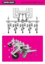
rester de chaque côté à égale distance des roues du tracteur (fig. ci-contre).
Si la bineuse a dévié, il faudra modifier légèrement l’orientation

des coutres stabilisateurs par le réglage  3  vers la droite si la bineuse

dévie à gauche et vers la gauche si la bineuse dévie à droite.

• Reprendre la conduite et vérifier de nouveau au bout de 10-20 m. Dès

qu’on a la certitude que la machine conserve la trajectoire du tracteur,

descendre les disques protège plants et parfaire l'enterrage des socs.

La bineuse sera alors prête, il faudra cependant savoir que, de par son

principe flottant, la machine ne déviera par la suite que difficilement de sa

trajectoire initiale. Il lui faudra une dizaine de mètres avant de répondre

aux sollicitations du tracteur. Le chauffeur devra donc en être conscient

lorsqu'il amorcera une courbe ou fera une erreur de conduite. Par contre,

les petits écarts du tracteur seront sans influence.

OPERATING INSTRUCTIONS 

(Important)

• The Row Crop cultivator, hitched to the tractor, with its toolbar stand raised,

should be used with the toolbar frame 70 cm (28") above the ground.

• The tractor lift arms should be in a floating position (chains slackened)

and be of the same length.

• Adjust the TOPLINK length for the units to be level on the ground , with

parallelogram arms horizontal.

• On the field, line up exactly with marked line left while planting.
• Lower the Row Crop cultivator. Lift the cultivator shields, drive forward

a  few  feet  and  then  check  if  all  spacing  adjustments  of  the  tines  and

discs are correct... if the working depth is good, if the penetration of the

stabilizing  coulters is sufficient. This penetration depends on the spring

compression   1  ; this adjustment is controlled by the crank  2  ; 10 cm (4")

penetration is adequate under normal conditions. 

• Drive  forward  again  about  10  meters  (30’)  and  check  if  the  Row  Crop 

cultivator  has  not  moved  from  its  position  to  the  tractor.  This  is

accomplished by  the  lift  arms.  Although  in  a  floating  position,  they

should remain on either side at equal distance from the tractor wheels

(fig. opposite).
If  the  Row  Crop  cultivator  has  moved,  the  setting  of  the  stabilizing

coulters should be slightly modified by the adjusting device  3  to the

right if the Row Crop cultivator moves to the left and to the left if the

Row Crop cultivator moves to the right.

• Drive again 10 to 20 m (30’-60’) and check. As soon as you are sure that

the  Row  Crop  cultivator  follows  straight  behind  the  tractor,  lower  the

rotating cultivator shields and make a last check about penetration and

working depth.

The  Row  Crop  cultivator  is  now  ready  to  start.  However  it  should  be

pointed out that due to its floating principle, the machine will not easily

move from its initial direction. It will require about ten meters (30’) before

responding to the direction of the tractor. The driver should therefore be

aware of this fact when taking a curve or if making a driving mistake. On

the contrary, small deviations of the tractor will have no influence.

INBETRIEBNAHME DER HACKMASCHINE

(Wichtig !)

• Hackmaschine an den Schlepper anbauen Abstellstütze hochstellen - die

Rahmenhöhe beträgt 70 cm.

• Die  Unterlenkerarretierungen  sind  nicht  festzustellen,  damit  die

Maschine hinter dem Schlepper frei nach links und rechts pendeln kann

(mit entspannten Ketten).

• Den  Oberlenker  so  einstellen,  daß  der  Oberlenkeranbaubock  genau

senkrecht steht.

• Fahren Sie mit den Schlepperrädern in die richtige Reihe und achten Sie

dabei auf den richtigen Abstand zu den Pflanzenreihen.

• Hackmaschine  auf  den  Boden  stellen,  die  Pflanzenschutzscheiben

hochhängen, ein paar Meter fahren, dann prüfen, ob die Einstellung von

Zinken- und Scheibenabständen richtig sind, ob die Arbeitstiefe stimmt

und  ob  das  Scheibensech  genügend  in  den  Boden  eindringt.  Das

Eindringen in den Boden richtet sich nach dem Druck der Feder  1  . Mit

der Kulber kann die Tiefe verstellt werden.

• Fahren  Sie  dann  noch  ein  paar  Meter  weiter  und  prüfen  Sie,  ob  die

Hackmaschine nach links oder rechts in eine Pflanzenreihe gelaufen ist.

Auf jeden Fall sollen die Unterlenkerarme den gleichen Abstand zu den

Hinterrädern haben.

• Sollte die Hackmascine nach links oder rechts gelaufen sein, so muß die

Richtung  der  Scheibenseche  verstellt  werden.  Dies  ist  durch  die

Einstelschraube  3  möglich.

• Fahren Sie jetzt weiter und kontrollieren Sie die Maschine wieder nach ca.

20 m. Sobald Sie sicher sind, daß die Hackmaschine der Richtung des

Schleppers  folgt,  stellen  Sie  die  Pflanzenschutzcheiben  herab  und  die

Tiefenregulierung der Schare ein.

Die Hackmaschine ist jetzt einsatzbereit. Durch die beiden Scheibensechs

wird die Maschine so stabilisiert, daß die Maschine in ihrer Anfangsrich-

tung schwer geändert wird. Sie braucht noch ungefähr 10 m bis sie der

Bewegung des Schleppers folgen kann. Der Fahrer muß die Bewegung

der Maschine kennen, wenn er eine Kurve fährt. Kleine Richtungsände-

rungen haben keine Einwirkung auf die Richtung der Hackmaschine.

AVVIAMENTO DELLA SARCHIATRICE

(Importante)

• La  sarchiatrice  attaccata  al  trattore,  con  il  sostegno  sollevato,  é  da

utilizzare con la trave posizionata a 70cm dal suolo.

• I bracci di sollevamento del trattore devono avere un movimento libero

(catene stese) e di lunghezza uguale.

• Aggiustare  il  terzo  punto  affinché  gli  elementi  siano  perpendicolari  al

suolo, con i bracci di parallelogrammi orizzontali.

• Presentarsi nel campo perfettamente in linea su una delle lunghezze di

lavoro effettuate dalla seminatrice.

• Posare la sarchiatrice, sollevare i dischi proteggi-piante, avanzare alcuni

metri poi verificare che gli aggiustamenti di intervalli dei denti e dischi 

corrispondano correttamente, che la profondità di lavoro sia buona, che la

penetrazione dei coltri stabilizzatori sia sufficiente. Questo interramento

dipende dalla compressione della molla  1  ; la manovella comanda questa

regolazione : una penetrazione di 10 cm é sufficiente nelle condizioni normali.

• Poi movere ancora la sarchiatrice circa dieci metri e controllare allora

che la macchina non abbia deviato dalla traiettoria imposta dal trattore.

Questo si controlla al livello dei bracci elevatori che, benché siano mobili,

devono rimanere ad ogni lato a iguale distanza dalle ruote del trattore (fig.

qui accanto).
Qualora la sarchiatrice avesse deviato, occorrerà modificare leggermente

l'orientazione dei coltri stabilizzatori tramite la regolazione  3  a destra se

la macchina devia a sinestra e a sinestra se la macchina devia a destra.

• Riprendere la guida e verificare di nuovo dopo 10-20m. Appena Lei é

certo che la macchina mantiene la traiettoria del trattoria, abbassi i dischi

proteggi-piante e aggiusti l'interramento dei vomeri.

La sarchiatrice é allora pronta. Tuttavia occorre sapere che a causa del suo

principio di movimento libero, la macchina devierà posteriormente con

difficoltà  dalla  traiettoria  iniziale.  Bisognerà  ca.  dieci  metri  prima  di

rispondere  alle  sollecitazioni  del  trattore.  Quindi  il  conduttore  dovrà

averne coscienza quando comincierà una curva o farà un errore di guida.

Invece  i  piccoli  scarti  del  trattore  non  avranno  nessuna  influenza  sulla

direzione della macchina.

Summary of Contents for SUPER-CROP C1L

Page 1: ...ly Adjustment and Maintenance Instructions Bedienungsanleitung Einstellung Wartung Notizia di Montaggio Regolazione Manutenzione BINEUSES DE PR CISION PRECISION ROW CROP CULTIVATORS BINEUSES DE PR CIS...

Page 2: ...e RIBOULEAU MONOSEM factory at the phone number given on the last page of this manual The identification and manufacturers plate on your cultivator is ti be found on the tree point hitch of the machin...

Page 3: ...EUER FERTILIZZATORE GRANDES TR MIES HIGH CAPACITY HOPPERS 38 39 GROSSRAUMBEH LTER TRAMOGGE GRANDI EXTRA FORT F LEGER V DIRIGEABLES EXTRA STRONG F LIGHT V STEERING EXTRA STARK F LEICHTE V HACKMASCHINE...

Page 4: ...ge et de d telage doivent se faire avec pr caution 11 Lors du d telage assurez vous du bon positionnement des b quilles pour une bonne stabilit de la machine 12 Avant l attelage de la machine assurez...

Page 5: ...et c t machine ne sont pas sous pression avant tout branchement de flexible au circuit hydraulique du tracteur 4 Afin d viter tout risque d inversion des fonctions ou erreur de branchement nous recomm...

Page 6: ...achine from the tractor 11 Before hitching up the machine ensure that the front axle of the tractor is sufficiently weighted Ballast weights should be fitted to the special supports in accordance with...

Page 7: ...guidelines 3 Before fitting a hose to the tractor s hydraulic circuit ensure that the tractor side and the machine side circuits are not pressurized 4 The user of the machine is strongly recommended...

Page 8: ...er Maschine am Schlepper geboten 11 Vor Anh ngen der Maschine kontrollieren ob der Ballast des Schleppers gen gt Die Ballastelemente m ssen gem den Vorschriften des Schlepperherstellers auf den daf r...

Page 9: ...ter Druck stehen 4 Dem Benutzer der Maschine wird zur Vermeidung falscher Anschl sse dringend geraten die Kennzeichnungen auf den Hydraulikanschl ssen zwischen Schlepper und Maschine zu beachten da so...

Page 10: ...o zavorramento dell assale davanti al trattore sia sufficiente La messa in atto di masse di zavorramento deve essere effettuata sui supporti previsti per questa operazione conformemente alle indicazio...

Page 11: ...di riferimento d identificazione sui raccordi idraulici tra il trattore e la macchina al fine di evitare errori di collegamento Attenzione Pu presentarsi il rischio di invertire alcune funzioni ad ese...

Page 12: ...NEN SARCHIATRICI DI PRECIZIONE BINEUSES DE PR CISION PRECISION ROW CROP CULTIVATORS PR ZISIONSHACKMASCHINEN SARCHIATRICI DI PRECIZIONE SCD 45 65 cm 65 80 cm C3 65 80 cm C3D 65 80 cm DF5 60 90 cm DF5 6...

Page 13: ...vator 65 80 cm 7 x 7 frame length 9 80 m 4 guiding discs 2 land wheels Sarchiatrice SCD 12 file mais 65 80cm telaio 7 x 7 Lunghezza 9 80 m 4 dischi di guida 2 ruote portanti Bineuse SCD 4 rangs ma s 6...

Page 14: ...12 AUTOGUID E SCD Fig 1 Fig 2 Fig 4 Fig 3 Fig 5 F D C C B E...

Page 15: ...hine 7 Mount the accessories cross bars tines discs following the instructions of the next page FOR OPERATING INSTRUCTIONS PLEASE REFER TO PAGES 16 17 MONTAGEANLEITUNG Die Hackmaschine SUPER CROP SCD...

Page 16: ...AUTOGUID E SCD 14 Fig 8 Fig 6 Fig 10 Fig 9 Fig 12 Fig 11 8 1 3 6 7 7 9 2 4 5...

Page 17: ...cm 6 are the basic SCD SUPER CROP accessories However it may be replaced by many other tools mould board shanks ridgers See page 24 25 and fig 9 opposite MONTAGE DER AUSR STUNGSTEILE Einstellung der E...

Page 18: ...AUTOGUID E SCD 16 Fig 13 Fig 14 3 2 1 3...

Page 19: ...urve or if making a driving mistake On the contrary small deviations of the tractor will have no influence INBETRIEBNAHME DER HACKMASCHINE Wichtig Hackmaschine an den Schlepper anbauen Abstellst tze h...

Page 20: ...DIRIGEABLES F V SCD 18 Fig 15 Fig 16 Fig 17 Fig 18 Fig 19 Extra Fort F Extra Strong F Extra Stark F Extra Forte F L ger V Light V Leichte V Leggero V 8 6 10 5 1 10 2 2 11 12 12 4 9 7 3...

Page 21: ...able by means of pins 11 according to the tools being used It is also possible to lock the steering for certain applications such as ridging by lifting part 12 then turning it 1 4 turn HACKMASCHINE MI...

Page 22: ...rs C3 5 dents flexibles ou rigides 3 dents flexibles ou rigides Outils sur supports flexibles Outils sur porte outils SC 3 c urs C3 3 c urs disques C3D Lames Leli vre C ur Butteur C3 65 80 cm DF5 60 9...

Page 23: ...mente Eine Hackmaschine besteht aus einer gewissen Anzahl ganzer Elemente mit Kompletter Ausr stung zum Hacken von kompletten Reihenabst nden und aus zwei seitlichen Elementen mit vereinfachter Ausr s...

Page 24: ...22 Fig 23 Fig 25 Fig 24 2 1 3 4 Bineuse houe 5 l ments avec direction Bineuse houe 3 l ments sans direction...

Page 25: ...auf Parallelogramm montiert und mit einem Tiefenbegrenzungsrad vorn ausger stet das starre Element wird nicht mehr benutzt Es ist auf einem Lenkrahmen angebracht wie die Elemente F V und SCD siehe Se...

Page 26: ...24 SCD F V Fig 26 Fig 27 Fig 28 SUPER CROP types F et V SUPER CROP SCD HOUE 1 5 6 7 8 2 3 4 1 5 2 3 4 1 5 6 7 2 3 4...

Page 27: ...r Hackmaschine SUPER CROP F und V Abb 26 1 G nsefur schare 14 20 25 und 30 cm breit 2 G nsefur schare 20 25 und 30 cm breit 3 Nasenwinkelschare f r Mais und R ben 4 Normale Winkelmesser Planet mit un...

Page 28: ...26 SCD F V BINEUSES FRONTALES Tracteur quip d un relevage avant Fig 33 Fig 30 Fig 31 Fig 32 4 3 3 3 Fig 29 Bineuse SCD 4 rangs pouss e avant 1 1 3 3 2 1 2 2...

Page 29: ...ation and in particular a daily lubrication of the 2 hubs of the front land wheels FRONTHACKMASCHINE AUF EINEM MIT FRONTHYDRAULIK AUSGER STETEN SCHLEPPER Bei Frontanbau ist ein Schlepper mit Vierrad A...

Page 30: ...28 F V BINEUSES FRONTALES avec quipement de relevage 4 4 7 6 1 5 2 3 Fig 36 Fig 37 Fig 35 Photo non contractuelle Fig 34 Fig 38...

Page 31: ...de in confronto alla sarchiatrice posteriore una potenza di trattore superiore In questo caso si raccomanda l uso di un trattore da 4 ruote motrici Le versioni F e V possono montarsi su questo tipo de...

Page 32: ...30 SCD F V CHASSIS A REPLIAGE MANUEL Fig 39 Fig 42 Fig 44 Fig 43 Fig 45 Fig 46 Fig 40 Fig 41 1 5 4 1 3 3 2...

Page 33: ...ing manual folding frame units with Leli vre blades and shovels of 30 cm on spring tines RAHMEN Von Hand einklappbar Es wird eine dreiteilige Werkzeugschiene geliefert wo die beiden Au enenden mit dem...

Page 34: ...32 SCD F V CHASSIS A REPLIAGE HYDRAULIQUE Fig 47 Fig 50 Fig 54 Fig 55 Fig 56 Fig 57 Fig 53 Fig 51 Fig 52 Fig 48 Fig 49 1 1 1 3 4 5 2 2 3...

Page 35: ...drei Au enelementen hydraulisch eingeklappt werden Die selbstgesteuerten Hackmaschinen und die Hackmaschinen mit Feinsteuerung lassen sich hydraulisch klappen Die Hackmaschinen F und V k nnen nur ein...

Page 36: ...34 SCD FERTILISEUR RECTANGULAIRE sur bineuse ch ssis rigide Fig 58 Fig 59 Fig 60 Fig 61 Fig 62 3 1 2 1 3...

Page 37: ...0 264 acre for most fertilizers ATTENTION Set the height of the toolbar so that there is adequate down pressure on the floating drive wheel however also make sure that the weight of the machine does n...

Page 38: ...ISEUR RECTANGULAIRE sur bineuse repliage manuel et hydraulique Fig 63 Fig 64 Fig 65 Fig 66 Fig 67 SCD 4 rangs 75 80 cm Repliage manuel SCD 6 rangs 75 80 cm Repliage manuel SCD 6 RANGS 75 80 CM REPLIAG...

Page 39: ...gen Abb 63 4 reihige Hackmaschine SUPER CROP SCD Mais 75 80 cm auf manuell klappbaem Rahmen zentrale Werkzneugstange 2 20m lang mit 6 Verbindungsstreben 0 345m lang Der D ngerstreuer der aus 2 Beh lte...

Page 40: ...38 SCD FERTILISEUR GRANDE CAPACIT sur bineuse SCD Fig 76 Fig 77 Fig 78 5 6 6 7 9 9 7 4 1 1 4 2 5 3 8...

Page 41: ...Granulat auf Hackmaschine SCD mit Steifrahmen 2 Modelle werden angeboten 1 SCD 4 reihige Hackmaschine 75 80 cm mit Gro d ngerstreuer von 1000 Litern ein einziger Beh lter aus Blech mit dichter Plane...

Page 42: ...1 600 1 700 1 800 1 900 2 000 2 100 2 200 RAPPORT 1 D bits l hectare suivant les types d engrais A1 40 50 60 70 80 90 100 110 120 130 B1 45 60 70 80 90 105 115 125 140 150 C1 60 80 95 110 120 140 160...

Page 43: ...enutzen Sie nur Granulat von guter Qualit t D NGERSTREUER MIT 1 STUFIGEM ANTRIEB Abb 79 Hackmaschine mit Kunstoff D ngerstreuer ohne Ray Grass Ausr stung I Benutzen Sie das Verh ltnis A1 Zahnrad A 35...

Page 44: ...42 SCD BINEUSE AUTODIRIG E Fig 86 Fig 89 Fig 93 Fig 90 Fig 91 Fig 92 Fig 88 Fig 87 5 4 4 2 3 11389 11389 11389 11389 11520 1 1...

Page 45: ...ing page 5 Rear tracing disc to be left in place if the user wants to cultivate again MONTAGEANLEITUNG Die Montage der Hackelemente erfolgt wie bei den klassischen Hackmaschinen Sehen Sie dazu die Anw...

Page 46: ...44 SCD BINEUSE AUTODIRIG E SCH MA LECTRIQUE Fig 94 Fig 97 Fig 96 Fig 95 Fig 98 2 1...

Page 47: ...TROMANSCHLU Auf Standardsteckdose 7 Stifte Abb 96 Seite 44 Erdung 3 Plus 7 an den Standlichten Die Versorgung Plus kann auf die best ndige Plus 2 angeschlossen werden Daf r ist die Steckdose bei Bedar...

Page 48: ...bstschmierenden Kugellagern ausger stet die nicht geschmiert werden brauchen Die Naben der glatten Schutzscheiben und der Abr umscheiben sowie die Gelenkachsen der Lenkung wenn die Hackmaschine damit...

Reviews: