


23
BINEUSES TYPE HOUE
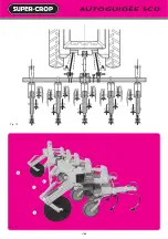
L’élément houe est monté sur parallélogramme, et équipé d’une
roue de jauge réglable à l’avant (l’élément rigide n’existe plus). Il
se monte sur un châssis dirigeable, comme les éléments "F", "V"
et "SCD" - voir pages 18-19. Il existe une version simplifiée, sans
direction. Le châssis est alors composé d’une barre porte-outils
avec un attelage à broches seulement Fig. 25.
Sur une telle bineuse, tous les éléments (centraux et latéraux)
sont à équipements complets, dont le plus courant se compose
de 5 dents rigides soc "Houe" 2 Fig. 23.
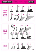
D’autres équipements sont possibles : 5 dents rigides à soc
pointu - 4 dents "Houe" + 1 "Patte d’oie centrale" - 3 dents au lieu
de 5 - 3 dents + lames - Butteurs F35 ou AM… (voir ces différents
outils page suivante).
Des 1/2 inter-rangs latéraux peuvent être montés si besoin. Le
réglage du terrage se fait par la hauteur des outils d’une part et
par la hauteur des roues jauges d’autre part 1 . Une manivelle
arrière 4 règle sur chaque élément et pour tous les outils à la fois
la largeur de travail. La hauteur du châssis est réglable en
fonction des outils utilisés au travail, les parallélogrammes
doivent être horizontaux : agir sur les roues 3 .
HOE-TYPE CULTIVATORS
The hoe unit is assembled on a parallelogram and is equipped
with an adjustable front gauge wheel (the rigid unit is no longer
used). It is assembled on a steering frame in the same way as the
"F", "V" and "SCD" units - see pages 18-19. There also exists a
simplified version without steering. The frame is the made up of
just a toolbar with a hitch with pins Fig 25.
On this type of cultivator, all the units (central and lateral) are
entirely equipped, the most common equipment being made up
of 5 rigid tines with "Hoe" share 2 Fig 23.
Other accessories are possible : 5 tines with pointed share -
4 "Hoe" tines + 1 central "Duckfoot" - 3 tines instead of 5 - 3 tines
+ blades - F35 or AM ridgers… (see these different tools on the
next page).
If needed, 1/2 lateral interrows can be mounted. The working
depth adjustment is controlled firstly by the height of the tools and
secondly by the height of the gauge wheel 1 . A rear crank 4 adjusts
the working width of all units simultaneously. The height of the
frame is adjusted according to the tools used, when working the
parallelograms should be horizontal : adjust the wheels 3 .
HACKMASCHINEN HACK-TYP
Das Hackelement ist auf Parallelogramm montiert und mit einem
Tiefenbegrenzungsrad vorn ausgerüstet - das starre Element wird
nicht mehr benutzt. Es ist auf einem Lenkrahmen angebracht, wie
die Elemente "F", "V" und "SCD" - siehe Seiten 18-19. Es gibt eine
vereinfachte lenkungslose Ausführung. Dabei besteht der
Rahmen aus einer Werkzeugsschiene mit nur einer Stiftenkup-
plung Abb. 25.
Bei dieser Hackmaschine werden nur ganze Elemente (zentrale
und seitliche) mit kompletter Ausrüstung verwendet. Serienmäßig
sind die Elemente mit 5 starren Zinken (Hackschar) Abb. 23.
Andere Ausrüstungen sind möglich : 5 starre Zinken mit spitzem
Schar - 4 starre Hack 1 zentrales Gänsefuß - 3 Zinken anstatt
5 - 3 Winkelmesser - Häufelkörper F35 oder AM… (für
diese verschiedenen Werkzeuge sehen Sie nächste Seite).
Nach Bedarf lassen sich natürlich halbe seitliche Elemente
montieren. Die Einstellung der Tiefenregulierung erfolgt
einerseits durch die Höhe der Werkzeuge und andererseits durch
die Höhe der Führungsrollen 1 . An jedem Element ist hinten eine
Kurbel angebracht, mit der die Arbeitsbreite aller Werkzeuge
verstellt werden kann. Die Höhe des Rahmens ist je nach den
während der Arbeit benutzten Werkzeugen einstellbar. Die
Parallelogramme müssen horizontal sein, um die Räder 3 zu
bewirken.
SARCHIATRICE TIPO ZAPPATRICE
L'elemento zappa viene montato su parallelogramma e munito
alla parte anteriore da una ruota di profondità regolabile
(l'elemento rigido non esiste più). Si monta su un telaio guidabile
come gli elementi "F", "V" e "SCD" - veda pagine 18-19. Esiste una
versione semplificata senza guida. In questo caso il telaio consta
soltanto di una barra portaattrezzi con un attacco a perni Fig. 25.
Su tale sarchiatrice, tutti gli elementi (centrali e laterali) hanno
attrezzi completi, il più corrente dei quali si compone di 5 denti
rigidi vomere "Zappa" (2) Fig. 23.
Altri attrezzi sono possibili : 5 denti rigidi con vomere a punta -
4 denti "Zappa" + 1 "Piede d'oca centrale" - 3 denti invece di 5 - 3
denti + lame - Rincalzatori F35 o AM… (veda questi differenti
attrezzi alla pagina seguente).
Si possono montare 1/2 interfile laterali se fosse necessario. La
regolazione dell'interramento si fa tramite l'altezza degli attrezzi
da una parte e tramite l'altezza delle ruote di profondità dall'altra
1 . Una manovella posteriore 4 aggiusta la larghezza di lavoro su
ogni elemento e per tutti gli attrezzi simultaneamente. L'altezza
del telaio é regolabile in funzione degli attrezzi utilizzati nel
lavoro; i parallelogrammi devono essere orizzontali. Perciò agire
sulle ruote 3 .
Summary of Contents for SUPER-CROP C1L
Page 14: ...12 AUTOGUID E SCD Fig 1 Fig 2 Fig 4 Fig 3 Fig 5 F D C C B E...
Page 16: ...AUTOGUID E SCD 14 Fig 8 Fig 6 Fig 10 Fig 9 Fig 12 Fig 11 8 1 3 6 7 7 9 2 4 5...
Page 18: ...AUTOGUID E SCD 16 Fig 13 Fig 14 3 2 1 3...
Page 46: ...44 SCD BINEUSE AUTODIRIG E SCH MA LECTRIQUE Fig 94 Fig 97 Fig 96 Fig 95 Fig 98 2 1...


