


“F” • “V”
29
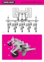
BINEUSE FRONTALE SUR TRACTEUR
NON MUNI DE RELEVAGE AVANT
Pour être conduite efficacement, une bineuse frontale demande,
comparativement à une bineuse arrière, une puissance de tracteur
supérieure. Un tracteur à 4 roues motrices est dans ce cas conseillé.
Seules les bineuses "F" et "V" peuvent être adaptées sur ce type de
relevage. Montages possibles, 4 rangs maïs, 6 rangs betterave rigide
(barre porte-outils 4,50 m maximum). L’équipement frontal se
compose d’un bloc porte vérin avec bielle 1 et 2 bras de poussée 2 ,
d’un cadre d’attelage automatique Fig 35 et d’un effaceur de traces
de tracteur Fig 38. Prévoir une pièce d’appui en 3 avec fixation au
niveau de la chape du tracteur. Prévoir également de chaque côté
1 ou 2 tirants stabilisateurs 4 .
☞
Une fois monté, le cadre doit être parfaitement vertical, l’axe
des bras inférieurs 5 à 70 cm du sol maximum (IMPORTANT).
Placer les bras de poussée 2 Fig. 37 le plus écarté possible, brides
avec articulation libre à l’avant. Aucun réglage n’est à faire sur ce
châssis en dehors du 3
ème
point et de la hauteur des roues pneu.
Veiller au bon alignement des bras de poussée afin de ne pas créer
de contraintes mécaniques excessives. Avant de partir en campagne,
ne pas oublier le graissage général, en particulier le graissage quotidien
des moyeux de roues porteuses avant, des roues d’éléments et des
parallélogrammes.
Fig. 36 - Mise en place de la béquille 6 avant décrochage par les
taquets 7 .
FRONT MOUNTED CULTIVATOR
ON TRACTOR WHICH IS NOT EQUIPPED
WITH A FRONT LINKAGE
To be efficiently operated, a front mounted cultivator, compared to a
rear mounted, requires more tractor power. In this case, a 4-wheel
drive tractor is recommended.
Only the "F" and "V" versions can be assembled on such a tractor. The
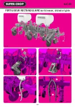
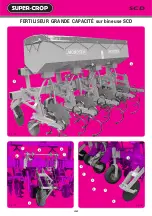
possible assemblies : 4-row SCD rigid cultivator for maize, 6-row rigid
model for sugarbeet (maximum of 4,50 m bar). The equipment
consists of hydraulic frame with rod 1 and 2 lift arms 2 , an
automatic hitch frame Fig. 35 and tractor track eradicators Fig. 38. A
support part in 3 with fixation on the tractor fork should be
envisaged. Also required, would be 1 or 2 stabilizing tie-rods on
either side 4 .
☞
Once assembled, the frame should be perfectly vertical, the
pins on the lower arms 5 to 70 cm maximum from the ground
(IMPORTANT).
Position the lift arms 2 Fig. 37 as far apart possible to allow for free
front articulation.
Check that the push arms are correctly in line with the lift arms so as
to avoid any mechanical stress. Before starting up, do not forget a
general lubrication and in particular a daily lubrication of the 2 hubs
of the front land wheels, the unit wheels and the parallelograms.
Fig. 36 – Positioning of the stand 6 before unhitching using the pins
7 .
SARCHIATRICE FRONTALE
SU TRATTORE NON EQUIPAGGIATO
DI UN SISTEMA DI SOLLEVAMENTO
ANTERIORE
Per essere guidata efficacemente, la sarchiatrice frontale richiede in
confronto alla sarchiatrice posteriore una potenza di trattore superiore.
In questo caso si raccomanda l'uso di un trattore da 4 ruote motrici.
Le versioni "F"e "V" possono montarsi su questo tipo de rialzo. I
montaggi possibili : 4 file mais, 6 file barbabietola rigido (barra
portaattrezzi 4,50 m mass.). L'attrezzatura frontale consta di un
blocco portacilindro con biella 1 e 2 bracci di spinta 2 , di un telaio
di attacco automatico Fig. 35 e di un cancellatraccie di trattore Fig.
38. Prevedere un pezzo di appoggio in 3 con fissaggio al livello della
flangia del trattore. Prevedere anche 1 o 2 tiranti stabilizzatori 4 a
ciascun lato.
☞
Montato, il telaio deve essere perfettamente verticale, essendo
l'asse dei bracci inferiori 5 a una distanza massima di 70 cm dal
suolo. (IMPORTANTE!)
Collocare i bracci di spinta 2 Fig. 37 il più lontano possibile, flange
con articolazione libera nella parte anteriore. Nessuna regolazione é
necessaria su questo telaio, salvo il terzo punto e l'altezza delle ruote
pneumatici.
Far attenzione al corretto allineamento dei bracci di spinta con i bracci
di sollevamento allo scopo di non creare sollecitazioni mecaniche
eccessive. Prima di cominciare la stagione, non dimenticare la
lubrificazione generale in particolare la lubrificazione quotidiana dei
2 mozzi di ruote portanti anteriori, delle ruote di elementi e
parallelogrammi.
Fig. 36 - Collocazione del sostegno 6 prima dello sganciamento
tramite i pezzi 7 .
FRONTHACKMASCHINE AUF EINEM
NICHT MIT FRONTHYDRAULIK
AUSGERÜSTETEN SCHLEPPER
Bei Frontanbau ist ein Schlepper mit Vierrad-Antrieb
empfehlenswert, da die Hackmaschine mehr Kraft als bei
Hinteranbau braucht.
Nur die Hackmaschinen "F" und "V" können an diesem Hubtyp
angebracht werden. Die möglichen Montagen : 4-reihige
Hackmaschine Mais, 6-reihige starr (Werkzeugschiene 4,50 m max.).
Für diese Hack-maschine wird eine separate Fronthydraulik geliefert.
Diese besteht aus einem Hydraulikrahmen mit Hydraulikzylinder 1
und 2 Schubar-men 2 , einem automatischen Anbaurahmen Abb. 35
sowie einem Schlepperspurlockerer Abb. 38. Es ist empfehlenswert,
diesen automatischen Anbaurahmen zu verwenden, damit die
Hackmaschine schnell an- und abgebaut werden kann 3 . Verwenden
Sie für den automatischen Anbaurahmen 1 oder 2
Stabilisierungsstreben 4 .
☞
Montieren Sie den Rahmen senkrecht am Schlepper. Die Bolzen
der unteren Befestigungspunkte 5 sollten höchstens 70 cm vom
Boden entfernt sein. WICHTIG !
Die Schubarme sollen möglichst weit gestellt werden, um eine gute
Arbeit zu gewährleisten. Dazu sind die Stifte mit freiem Gelenk vorn
anzubringen. Der Rahmen braucht keine Verstellung. Nur der
Oberlenker und die Höhe der Reifenräder müssen angepaßt werden.
Achten Sie auf das richtige Ausrichten der Schubarme, damit keine
übermäßige mechanische Spannungen entstehen. Vor dem Beginn
der Arbeitssaison vergessen Sie nicht die Hauptschmierung
insbesondere die tägliche Schmierung der Naben der 2
Fronttragräder, der Elementräder sowie der Parallelogramme.
Abb. 36 – Aufstellen der Abstellstütze 6 vor dem Entkuppeln mittels
der Vorrichtungen 7 .
Summary of Contents for SUPER-CROP C1L
Page 14: ...12 AUTOGUID E SCD Fig 1 Fig 2 Fig 4 Fig 3 Fig 5 F D C C B E...
Page 16: ...AUTOGUID E SCD 14 Fig 8 Fig 6 Fig 10 Fig 9 Fig 12 Fig 11 8 1 3 6 7 7 9 2 4 5...
Page 18: ...AUTOGUID E SCD 16 Fig 13 Fig 14 3 2 1 3...
Page 46: ...44 SCD BINEUSE AUTODIRIG E SCH MA LECTRIQUE Fig 94 Fig 97 Fig 96 Fig 95 Fig 98 2 1...


